Apparatus and method for heat-treatment of optical fiber reinforcing member and optical fiber fusion splicing apparatus

a technology of splicing apparatus and reinforcing member, which is applied in the direction of heater elements, instruments, optical elements, etc., can solve the problems of reducing affecting the heat capacity of the unit area, and affecting the cost and management of the reinforcing, so as to reduce the temperature difference between the contact part and the non-contact part and suppress the rise of the temperature of the non-contact part.

Active Publication Date: 2007-05-01
SUMITOMO ELECTRIC IND LTD
View PDF6 Cites 20 Cited by
  • Summary
  • Abstract
  • Description
  • Claims
  • Application Information

AI Technical Summary

Benefits of technology

[0013]The heat equalizing plate bonded to the heating portion of the sheet-like heating body reduces the difference in temperature between a contact part of the heating portion, with which the optical fiber reinforcing member makes contact, and a noncontact part thereof, with which the reinforcing-member makes no contact. Further, the heat equalizing plate suppresses the rise of the temperature of the noncontact part. Thus, the sheet-like heating body can be prevented from burning out. Furthermore, in a case where a fluorocarbon resin is coated on the surface of the heat equalizing plate, even when the thermal melting tube melts so that the molten resin adheres onto the heating body, the molten resin can easily be wiped away.
[0015]The difference in temperature between the contact part and the noncontact part can be decreased by reducing the heating value of the noncontact part of the sheet-like heating body, with which the optical fiber reinforcing member makes no contact. Thus, the rise of the temperature of the noncontact part can be suppressed. Consequently, the temperature of the sheet-like heating body can avoid rising to a temperature that is equal to or higher than a heat resistant temperature.

Problems solved by technology

Thus, this reinforcement has problems with cost and management.
However, this sheet-like heating body, which is formed by bonding a heating element to a surface of an organic resin film, is relatively small in heat capacity per unit area.
Therefore, there is a fear that the temperature of this part may excess a heat resistant temperature, and that thus, this part may burn out.

Method used


Image

  • Apparatus and method for heat-treatment of optical fiber reinforcing member and optical fiber fusion splicing apparatus
  • Apparatus and method for heat-treatment of optical fiber reinforcing member and optical fiber fusion splicing apparatus
  • Apparatus and method for heat-treatment of optical fiber reinforcing member and optical fiber fusion splicing apparatus

Examples


first embodiment

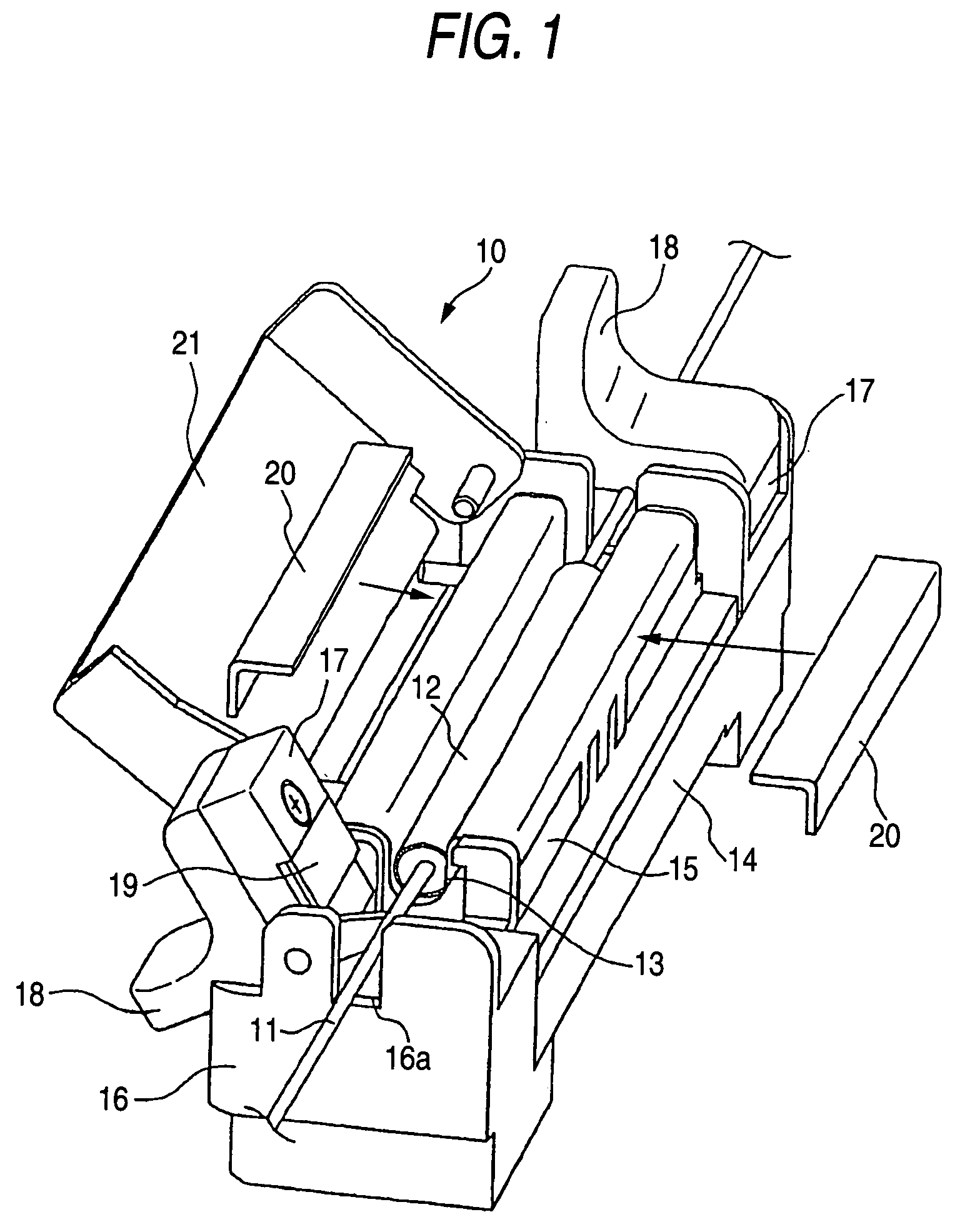
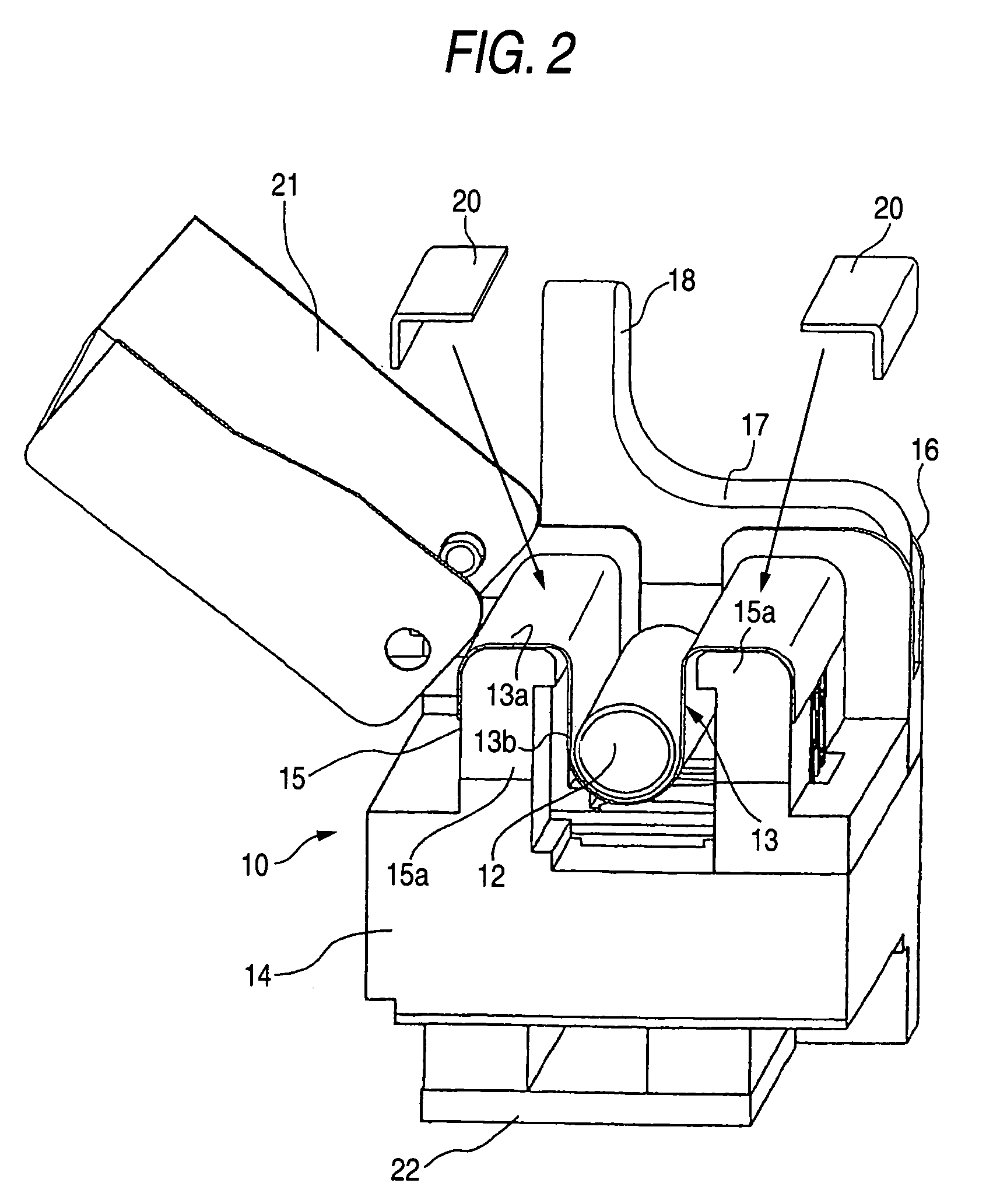
[0032]FIG. 1 is a view illustrating an apparatus for heat-treatment of an optical fiber reinforcing member according to the invention. FIG. 2 is a view illustrating a cross-sectional structure of the apparatus for heat-treatment, from which a part thereof shown in FIG. 1 is removed.

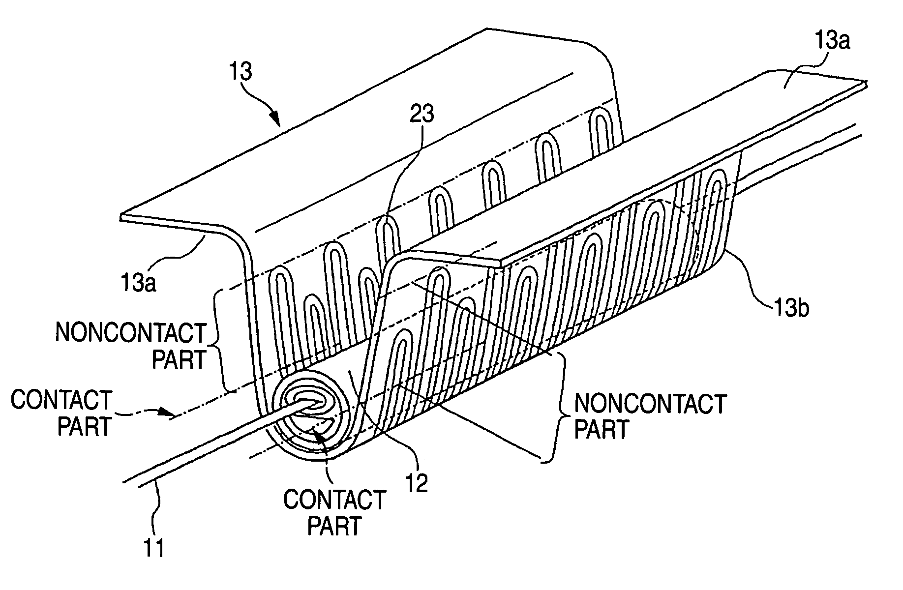
[0033]A heat-treatment apparatus 10 according to the first embodiment of the invention accommodates and supports a sheet-like heating body 13 for heating a reinforcing member 12 disposed in such a way as to protect fusion-spliced portion of single optical fibers or optical fiber ribbons 11 and the vicinity thereof. The reinforcing member 12 is constituted in such a manner as to accommodate a thermal melting tube, which is made of a hot melt adhesive resin, and a tensile strength member (referred to also as a reinforcing rod), which is made of a material, such as stainless steel, glass or ceramics, in a heat shrinkable tube, similarly to that shown in FIG. 15A. The sheet-like heating body 13 constituted by...

second embodiment

[0051]Next, the invention is described hereinbelow by referring to the drawings.

[0052]FIG. 6 is a view illustrating the second embodiment of an apparatus for heat-treatment of an optical fiber reinforcing member according to the invention. FIG. 7 is a view illustrating a cross-sectional structure of the apparatus for heat-treatment, from which a part thereof shown in FIG. 6 is removed.

[0053]As shown in FIGS. 6 and 7, a heat-treatment apparatus 110 according to the second embodiment of the invention has a sheet-like heating body 113, which has nonheating parts 113a and a heating part 113b, a base portion 14, a heating body supporting portion 15, which has supporting frames 15a, a clamp support 16, which has a groove portion 16a, a clamp piece 17, a lug portion 18, a grasping pad 19, pressure members 20, a cover 21, a circuit board 22, and a heat equalizing plate 125. Incidentally, members, which are the same as those of the heat-treatment apparatus 10 of the first embodiment of the i...


PUM


Abstract

A heat-treatment apparatus according to the present invention comprises a sheet-like heating body, which is bent like a letter “U”, and a heat equalizing plate constituted by a metal plate bonded to a heat generating part of the sheet-like heating body. The heat equalizing plate is bonded to the inner surface of the sheet-like heating body bent like a letter “U”. Alternatively, a fluorocarbon resin is coated on the surface of the heat equalizing plate.

Description

BACKGROUND OF THE INVENTION[0001]1. Field of the Invention[0002]The present invention generally relates to an apparatus and method for heat-treatment of an optical fiber reinforcing member, which reinforces optical fibers by covering a fusion-splicing portion therebetween with a sleeve-like protection member and by heat-shrinking the sleeve-like protection member, and to an optical fiber fusion-splicing apparatus.[0003]2. Description of Related Art[0004]Hitherto, the fusion-splicing of optical fibers has been performed by removing a fiber coating from a connecting end of each of the fibers and by heat-fusing exposed butting end parts of the bare fiber portions. The fusion-spliced bare fiber portions, from each of which the fiber coating is removed, are weak in mechanical strength and thus protected by reinforcing members. These reinforcing members are usually constituted by accommodating a thermal melting tube made of a thermal melting resin, to which a tensile strength member (refe...

Claims


Application Information

Patent Timeline
Patent Type & Authority Patents(United States)
IPC IPC(8): G02B6/00H05B3/58G02B6/255G02B6/38
CPCG02B6/2553G02B6/2558
Inventor SATO, RYUICHIRO
Owner SUMITOMO ELECTRIC IND LTD
Why Eureka
Try Eureka