Drive module and electronic device

a technology of electronic devices and drive modules, applied in the direction of printers, instruments, camera focusing arrangement, etc., can solve the problems of difficult use as a camera, and achieve the effects of improving the worth of the product, lowering the consumption power, and increasing the lens fram

Inactive Publication Date: 2011-09-29
SEIKO INSTR INC
View PDF34 Cites 20 Cited by
  • Summary
  • Abstract
  • Description
  • Claims
  • Application Information

AI Technical Summary

Benefits of technology

[0016]In view of the above, an object of the invention is to provide a drive module and an electronic device, which can restrain a rise of a lens frame, the rise being caused by an ambient environmental temperature, as well as restraining occurrence of an inclination of the lens frame in the case that no electricity is transmitted to the shape memory ally wire.
[0035]Furthermore, in accordance with the electronic device according to the invention, the drive module is provided. Accordingly, the electronic device can be used as a fixed focus camera, for example, even under a condition that no electricity is transmitted. This can improve the worth as a product as well as achieving lowering of consumption power.

Problems solved by technology

First, difference between the direction of urging the lens frame by the bias spring and a direction of an operation of the shape memory alloy wire for the lens frame causes the moment, and thereby, an inclination of the lens frame. Therefore, provided is a bias spring so that the both directions would be accorded.
This results in difficulty of use as a camera in the case of no electricity turned on.

Method used


Image

  • Drive module and electronic device
  • Drive module and electronic device
  • Drive module and electronic device

Examples


Embodiment Construction

(Drive Module)

[0054]Now, described will be an embodiment of a drive module in accordance with the invention, made reference to FIGS. 1 to 14.

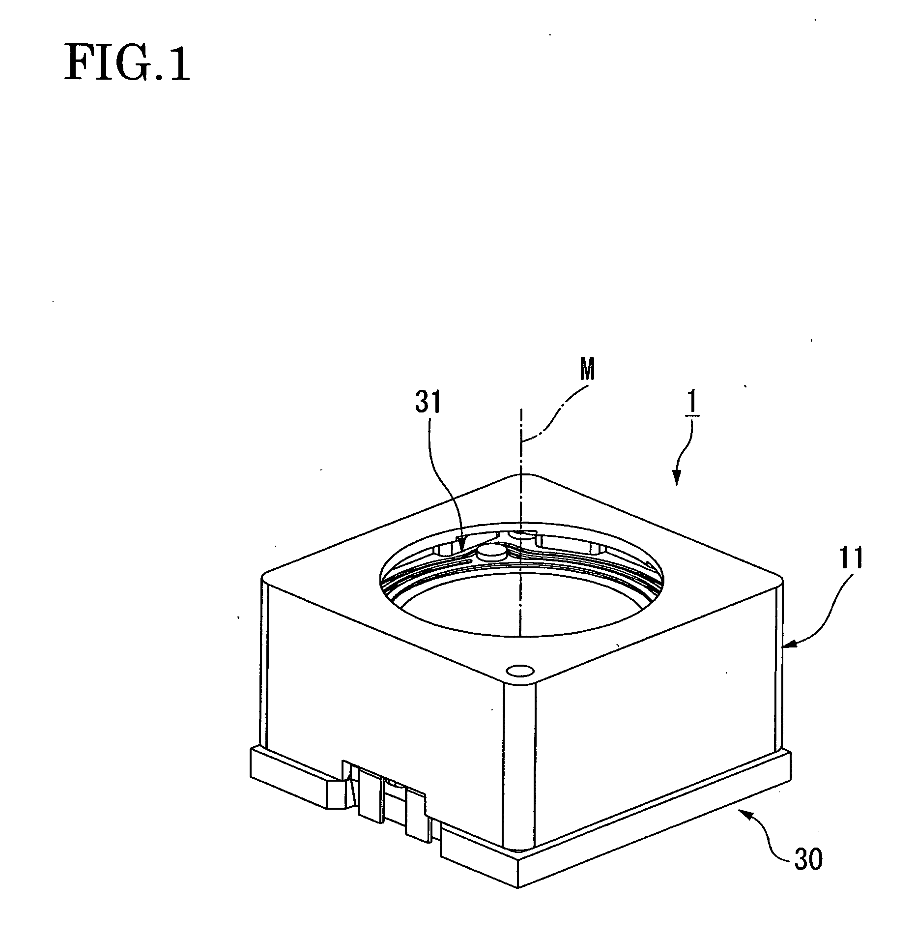
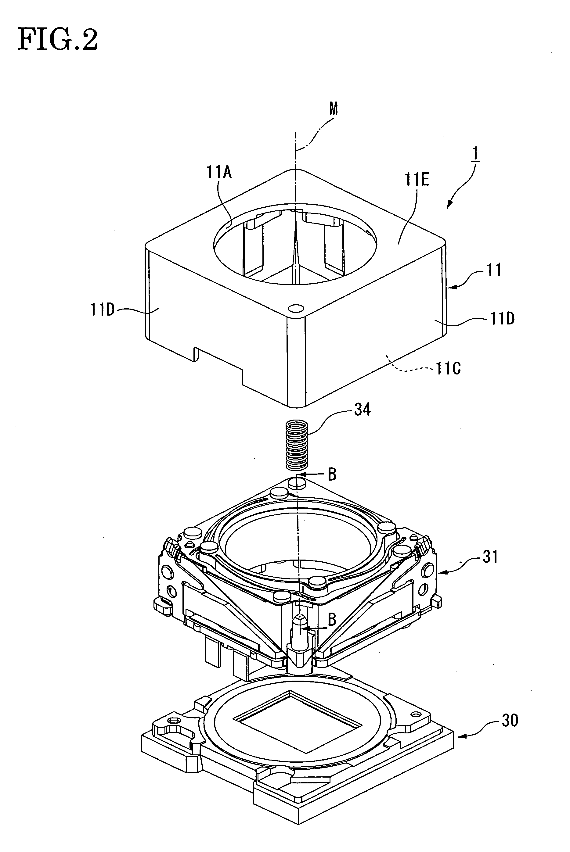
[0055]A drive module 1 in accordance with the embodiment is formed into the shape of a box as a whole, as shown in FIGS. 1 and 2. FIG. 1 is a perspective view of the drive module 1, showing an appearance thereof. FIG. 2 is an exploded perspective view of a schematic structure of the drive module 1.

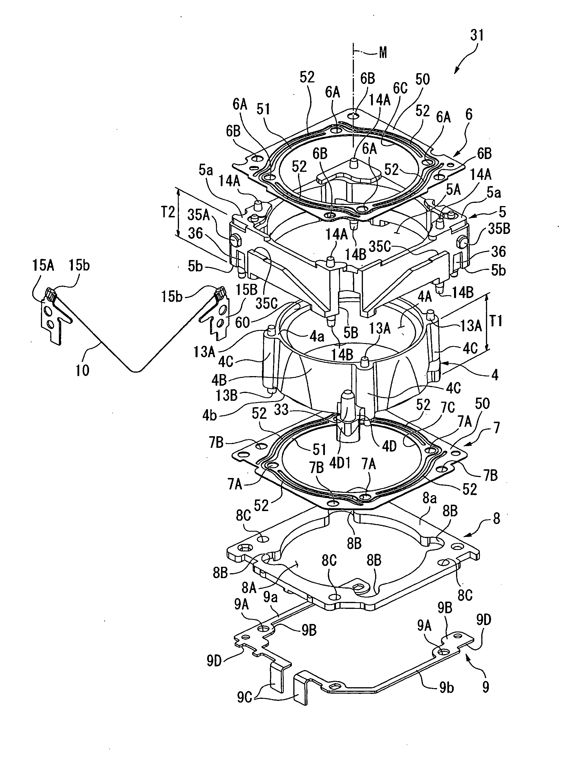
[0056]The drive module 1 is mounted to an electronic device or the like after completion of assembly. The drive module 1 is then fitted in or adhered to a substrate (not shown) for supplying the drive module 1 with a control signal and electric power to be fixed. The drive module 1 comprises an adaptor 30 located on the substrate, a drive unit 31 provided on the adaptor 30 and a cover 11 provided so as to cover the drive unit 31.

[0057]The drive unit 31 mainly comprises a lens frame 4, a module frame (a supporting member) 5, an upper leaf spring 6 and ...


PUM


Abstract

In order to restrain rising of a lens frame due to an ambient environmental temperature and occurrence of an inclination of the lens frame during transmission of no electricity to a shape memory alloy wire, proposed is a drive module including: a lens frame; a supporting member for storing the lens frame; leaf spring members for elastically holding the lens frame so that the lens frame would be movable with respect to the supporting member; a shape memory alloy wire for driving the lens frame toward one leaf spring member against restoring force of the leaf spring members by contraction due to generation of heat in turning on the electricity; and a bias spring member for urging the lens frame toward a base plate through a locking portion to make the lens frame come in contact with the base plate through the other leaf spring member, the drive module wherein the lens frame is provided with a pre-pressure portion for generating urging force for initially deforming one leaf spring member to urge the lens frame toward the base plate and for holding a balance with the bias spring member in the case of no electricity transmitted to the shape memory alloy wire to keep the contact condition of the lens frame.

Description

BACKGROUND OF THE INVENTION[0001]1. Technical Field[0002]The present invention relates to a drive module and an electronic device, particularly, a drive module and an electronic device, which are suitable for adjustment of a focal point by driving an optical system or a movable member or for a use as an actuator.[0003]2. Related Art[0004]In the related art, in a compact electronic apparatus such as a cellular phone with camera function or the like, proposed have been various kinds of drive module using a leaf spring to hold a driven member such as an image pickup lens unit so as to be movable in a direction of an optical axis while using expansion and contraction of a shape memory alloy wire to move the driven member in order to drive the driven member to perform autofocus, zooming and such.[0005]In a drive module disclosed in Patent Reference 1, for example, a lens frame (a driven member) inserted in a module frame (a supporting member) is held by means of two leaf springs so as to...

Claims


Application Information

Patent Timeline
Patent Type & Authority Applications(United States)
IPC IPC(8): G02B7/04
CPCG02B13/001G02B7/08G03B3/10H04N23/00
Inventor NOBE, TETSUYAUCHIBORI, TAKANOBUKOTANAGI, SUSUMU
Owner SEIKO INSTR INC
Why Eureka
Try Eureka