Liquid ejection apparatus

Active Publication Date: 2013-01-31
BROTHER KOGYO KK
View PDF1 Cites 20 Cited by
  • Summary
  • Abstract
  • Description
  • Claims
  • Application Information

AI Technical Summary

Benefits of technology

[0007]It is therefore an object of the present invention to provide a

Problems solved by technology

When the recording medium comes into contact with the head, it is possible that

Method used


Image

  • Liquid ejection apparatus
  • Liquid ejection apparatus
  • Liquid ejection apparatus

Examples


Embodiment Construction

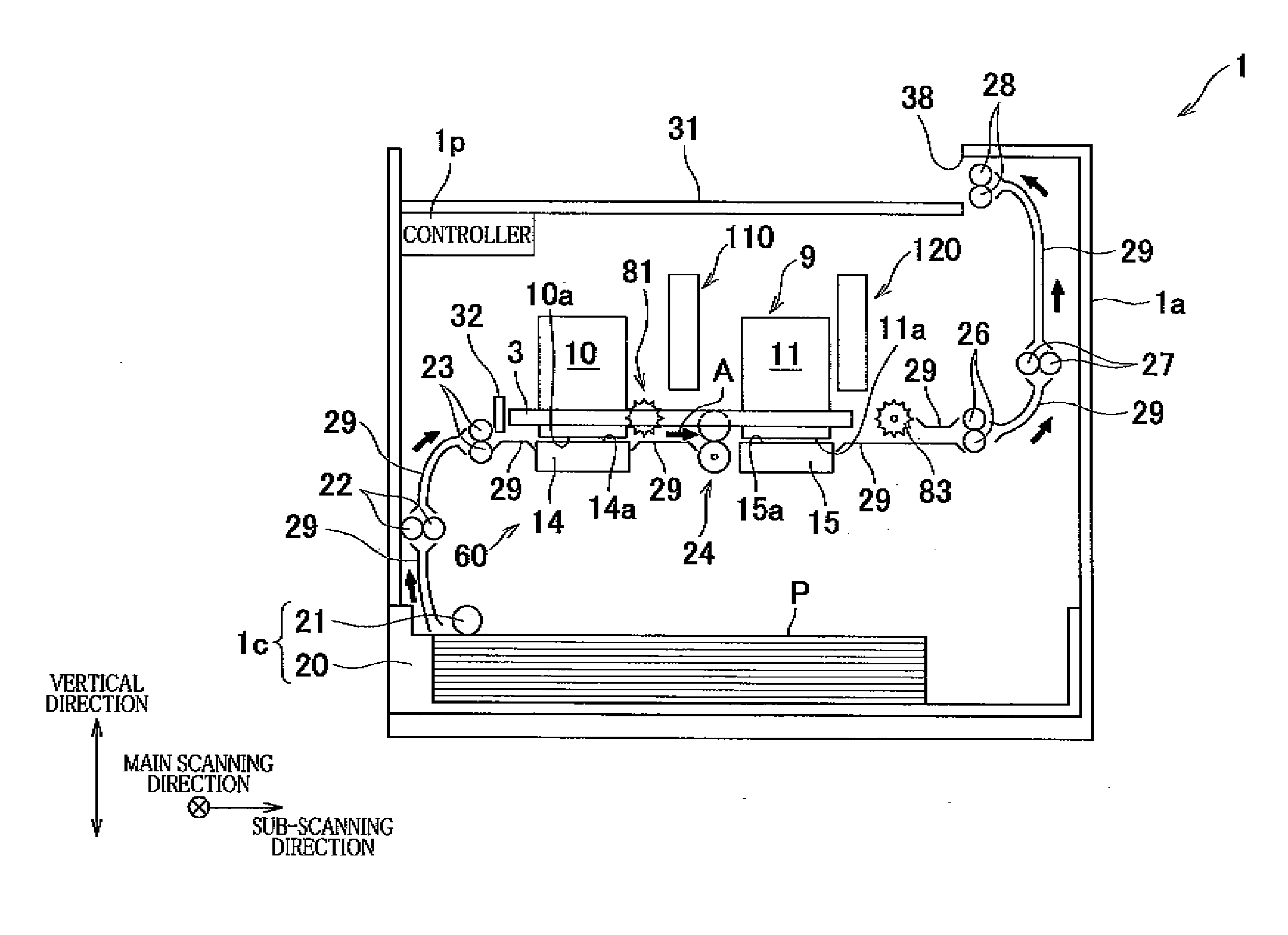
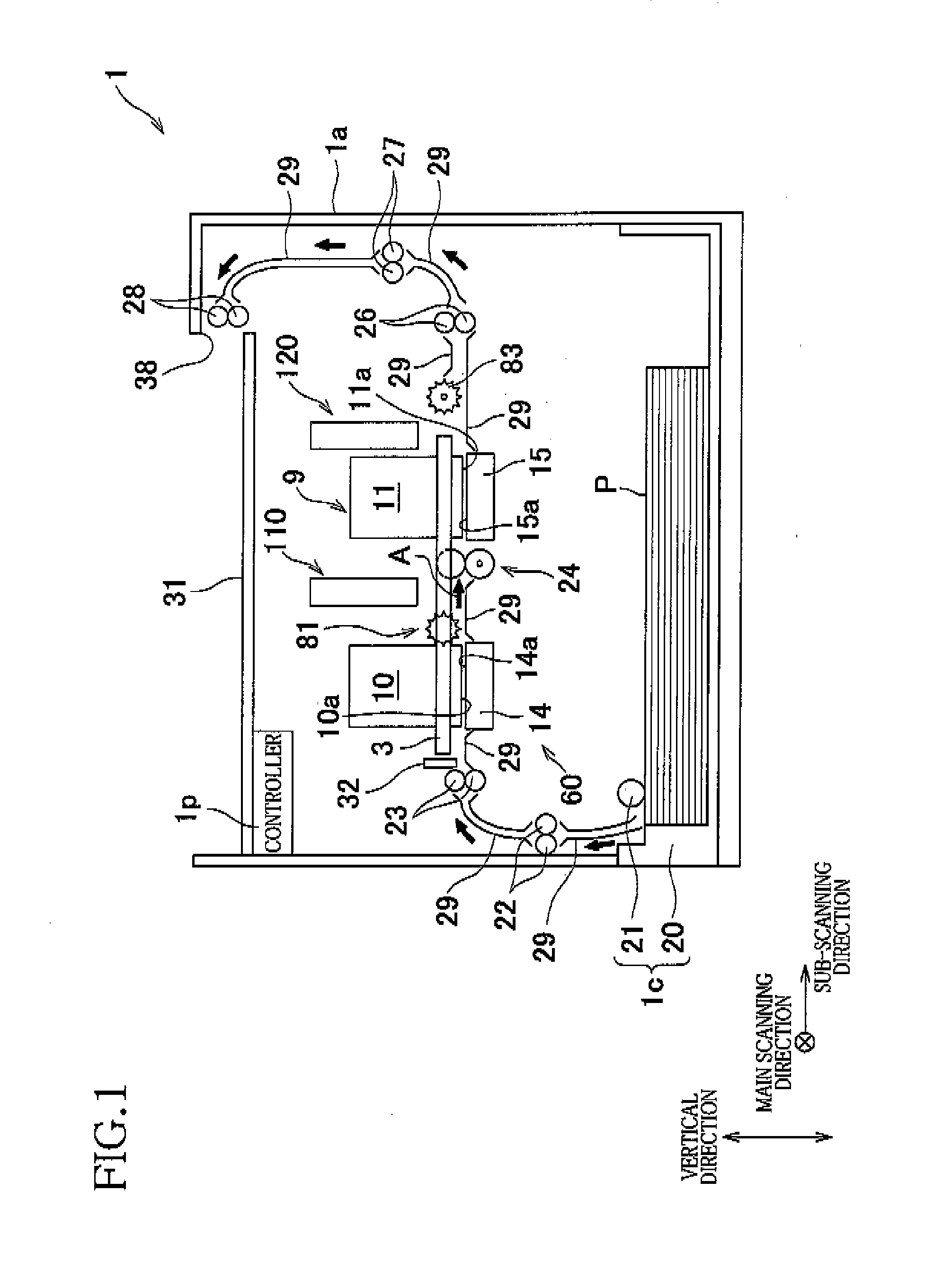
[0015]Hereinafter, there will be described embodiments of the present invention with reference to the drawings. An overall structure of an inkjet printer 1 as one embodiment to which the present invention is applied will be described with reference to FIG. 1.

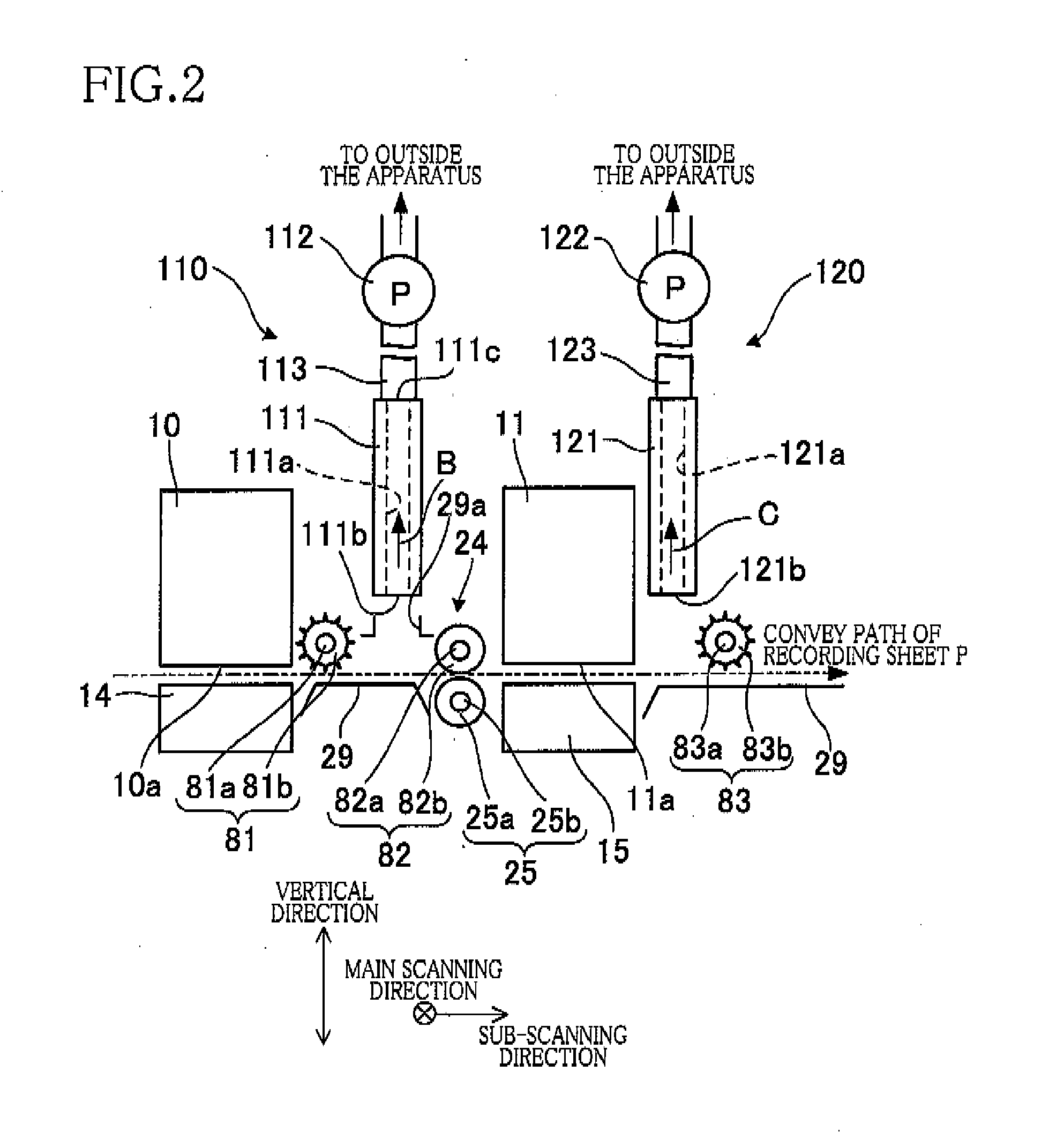
[0016]The inkjet printer 1 includes a casing 1a having a rectangular parallelepiped shape. In an upper portion of a top panel of the casing 1a, there is provided a sheet-discharge portion 31. In a space defined by the casing 1a, there is formed a sheet conveying path through which a recording sheet P as an example of a recording medium is conveyed from a sheet-supply unit 1c (described later) to the sheet-discharge portion 31 along a thick arrow A in FIG. 1. In the vicinity of the sheet conveying path, there are disposed a pre-coat head 10 and an inkjet head 11 as examples of liquid ejection heads, a conveyor mechanism 60 for conveying the recording sheet P, and so on.

[0017]The pre-coat head 10 is a line-type head having a gener...


PUM


Abstract

A liquid ejection apparatus includes: a conveyor mechanism conveying a recording medium in a conveying direction; a plurality of liquid ejection heads each having an ejection face from which a liquid is ejected and arranged in the conveying direction; a support member opposed to the ejection face and supporting the recording medium; a first suction mechanism which has a first suction opening located between two of the plurality of liquid ejection heads adjacent to each other in the conveying direction, and which sucks air via the first suction opening; and at least one first contact member located between the two liquid ejection heads in the conveying direction and contactable with a recording face of the recording medium at a position closer to the support member than the first suction opening in a direction perpendicular to the ejection face.

Description

CROSS REFERENCE TO RELATED APPLICATION[0001]The present application claims priority from Japanese Patent Application No. 2011-167036, which was filed on Jul. 29, 2011, the disclosure of which is herein incorporated by reference in its entirety.BACKGROUND OF THE INVENTION[0002]1. Field of the Invention[0003]The present invention relates to a liquid ejection apparatus having a liquid ejection head for ejecting a liquid.[0004]2. Discussion of Related Art[0005]There is known a liquid ejection apparatus in which mist produced by a liquid ejection is moved upward by sucking air between a plurality of heads for ejecting a liquid.SUMMARY OF THE INVENTION[0006]In a case where an airflow generating means is disposed near the heads, due to the airflow, it is possible that a recording medium rises from a support surface and comes into contact with the head. When the recording medium comes into contact with the head, it is possible that the head is damaged or an image recorded on the recording m...

Claims


Application Information

Patent Timeline
IPC IPC(8): B41J2/165
CPCB41J3/543B65H9/006B41J29/38B41J11/005
Inventor YAMAMOTO, SHINYASUGIMOTO, KIYOSHIOKUMURA, MASAYUKITSUBOI, MOTOHIRO
Owner BROTHER KOGYO KK
Why Eureka
Try Eureka