
Bicycle control device

a control device and bicycle technology, applied in the direction of mechanical control devices, cycle brakes, instruments, etc., can solve the problems of difficult operation of difficulty for some riders, and difficulty in adjusting the release lever of the control device illustrated in these patents, etc., to achieve the effect of easy shifting

Active Publication Date: 2006-09-05
SHIMANO INC
View PDF32 Cites 52 Cited by
  • Summary
  • Abstract
  • Description
  • Claims
  • Application Information

AI Technical Summary

Benefits of technology

[0008]One object of the present invention is to provide a control device that is easy to shift.
[0009]Another object of the present invention is to provide a compact and inexpensive bicycle control device that allows the rider to carry out braking and speed change operations without difficulty.

Problems solved by technology

However, the control devices illustrated in these patents have a large angle between the shift pivot axis and the operating portion of the shift lever used to wind the shift cable.
This arrangement results in the rider having to push the shift lever along a path that can be difficult for some riders.
Likewise, the release levers of the control devices illustrated in these patents are not arranged in the most advantageous position for the rider to operate.
Thus, the release lever of the control devices illustrated in these patents can be difficult for some riders to operate.

Method used


Image

  • Bicycle control device
  • Bicycle control device
  • Bicycle control device

Examples


Embodiment Construction

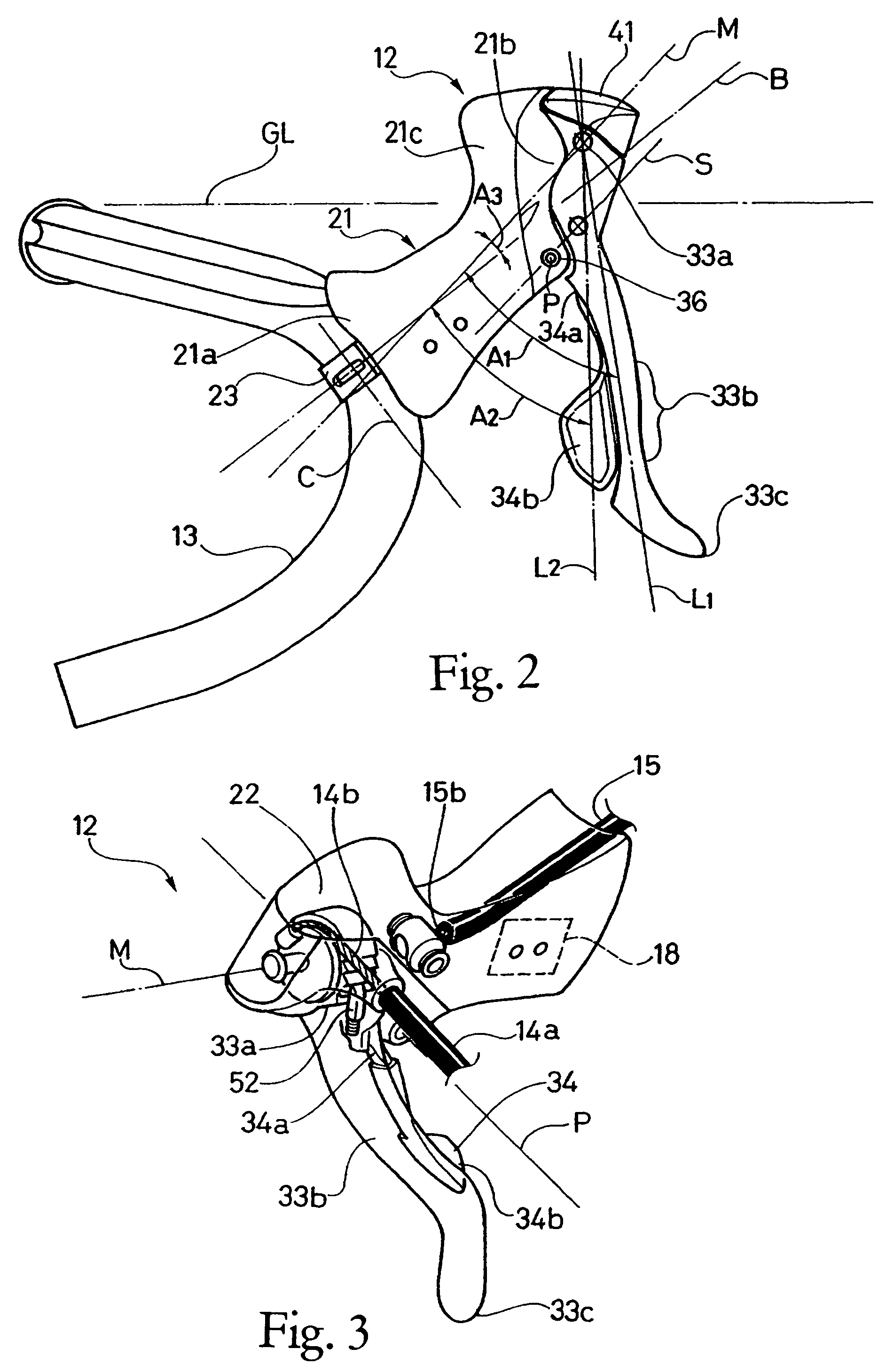
[0025]Selected embodiments of the present invention will now be explained with reference to the drawings. It will be apparent to those skilled in the art from this disclosure that the following descriptions of the embodiments of the present invention are provided for illustration only and not for the purpose of limiting the invention as defined by the appended claims and their equivalents.

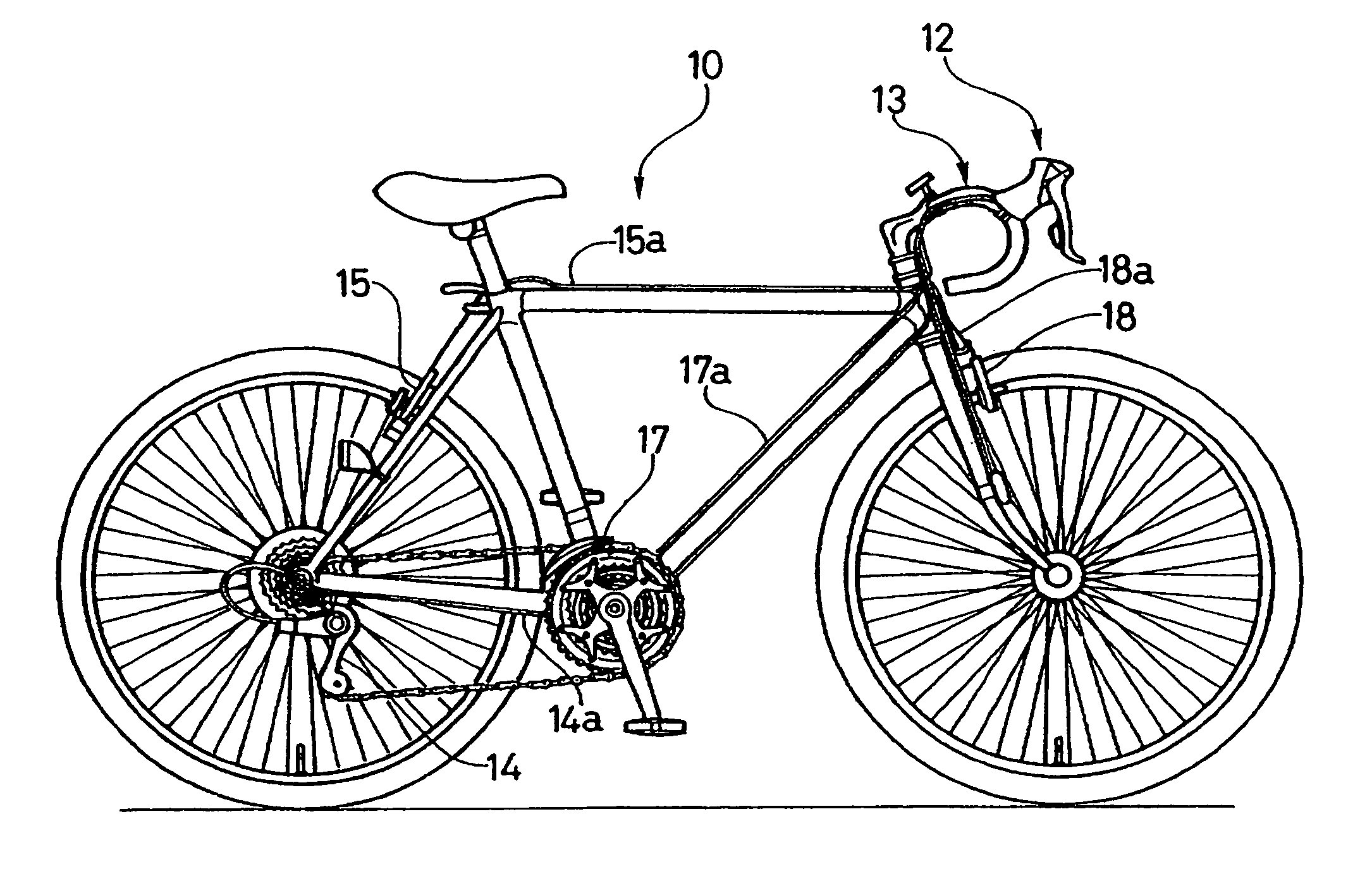
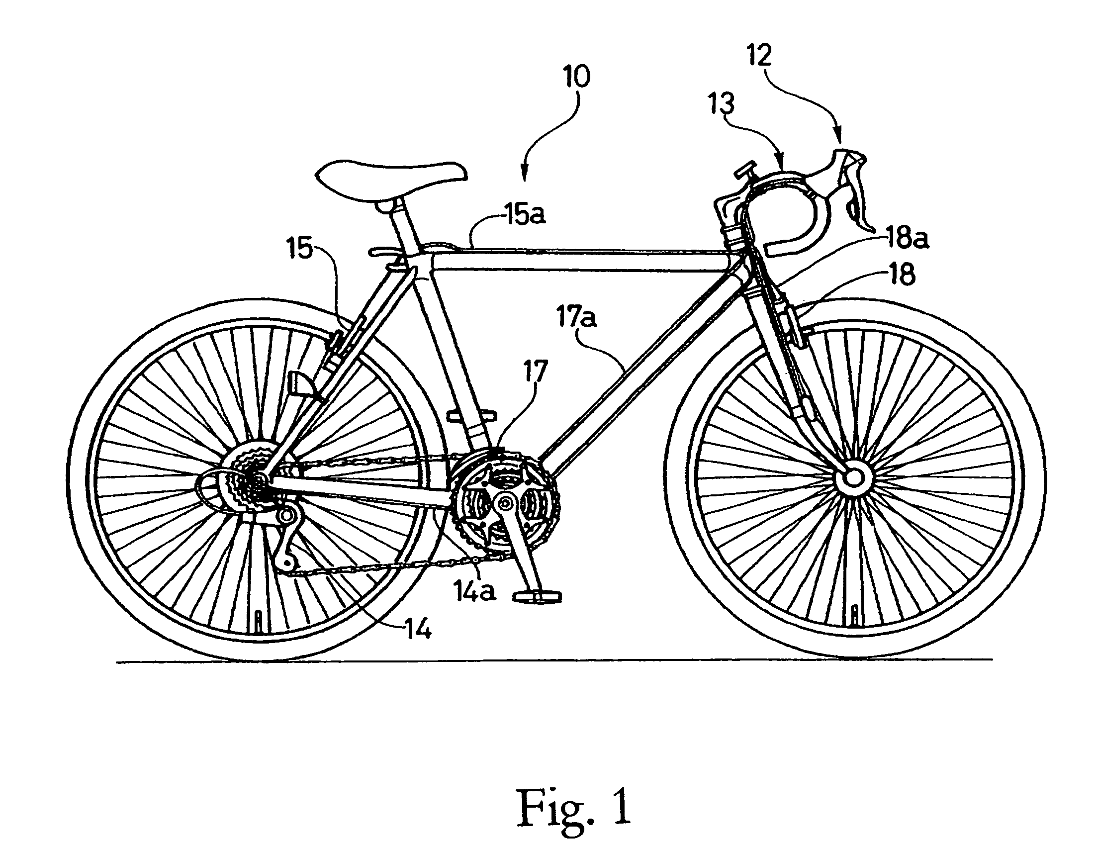
[0026]Referring initially to FIG. 1, a bicycle 10 is illustrated with a pair of control devices 12 (only one shown in FIG. 1) mounted in a bicycle handlebar 13 in accordance with one embodiment of the present invention. The right hand side control device 12 is operatively coupled to a rear derailleur 14 via a shift cable 14a and a rear braking device 15 via a brake cable 15a, while the left hand side control device 12 is operatively coupled to a front derailleur 17 via a shift cable 17a and a front braking device 18 via a brake cable 18a. The right and left hand side control devices 12 are essentia...


PUM


Abstract

A control device is configured to be attached to the handlebar of a bicycle for controlling a brake mechanism and change speed mechanism. The control device comprises a bracket fixed to the handlebar, a brake lever pivotally coupled crosswise relative to the bracket and a release lever. The brake mechanism is controlled by fore and aft pivotal movement of the brake lever, while the change speed mechanism is controlled by sideways pivotal movement of the brake lever and the release lever. The brake lever and the release lever are further configured relative to the bracket for smooth easy operation by the rider.

Description

BACKGROUND OF THE INVENTION[0001]1. Field of the Invention[0002]This invention generally relates to a bicycle control device for shifting gears to change the speed of the bicycle. More specifically, the present invention in a preferred embodiment relates to a bicycle control device that includes both braking and / or speed changing functions.[0003]2. Background Information[0004]Bicycling is becoming an increasingly more popular form of recreation as well as a means of transportation. Moreover, bicycling has become a very popular competitive sport for both amateurs and professionals. Whether the bicycle is used for recreation, transportation or competition, the bicycle industry is constantly improving the various components of the bicycle as well as the frame of the bicycle. Control devices for braking and / or shifting have been extensively redesigned in recent years.[0005]In the past, brake levers and shifting devices were separate devices that were attached to the handlebar and / or fra...

Claims


Application Information

Patent Timeline
Patent Type & Authority Patents(United States)
IPC IPC(8): G05G11/00F16C1/10B62K23/06B62L3/02B62M25/02B62M25/04
CPCB62K23/06B62L3/02Y10T74/20438
Inventor IRIE, YOSHINORISATO, HISAYUKI
Owner SHIMANO INC
Learn More