Variable valve timing controller

a timing controller and variable valve technology, applied in the direction of valve arrangement, yielding coupling, coupling, etc., can solve the problems of unnecessarily varying the rotational phase of the driven shaft relative to the driving shaft, and the durability of the vvt controller is deteriorated, so as to achieve high durability

Active Publication Date: 2006-09-05
TOYOTA JIDOSHA KK +1
View PDF3 Cites 16 Cited by
  • Summary
  • Abstract
  • Description
  • Claims
  • Application Information

AI Technical Summary

Benefits of technology

[0007]The present invention is made in view of the above matters, and it is an object of the present invention to provide the VVT controller which restricts rotational-phase fluctuations of the driven shaft if the force is applied to the phase adjusting mechanism, and has a high durability.

Problems solved by technology

When an engine torque is varied and some forces are applied to the phase adjusting mechanism, the operation member may slide in the groove so that the rotational phase of the driven shaft unnecessarily varies relative to the driving shaft.
When some forces are applied to the arms, the arms tend to be bent in its width direction, so that durability of the VVT controller is deteriorated.

Method used


Image

  • Variable valve timing controller
  • Variable valve timing controller
  • Variable valve timing controller

Examples


Embodiment Construction

[0027]Embodiments of the present invention will be described hereinafter with reference to the drawings.

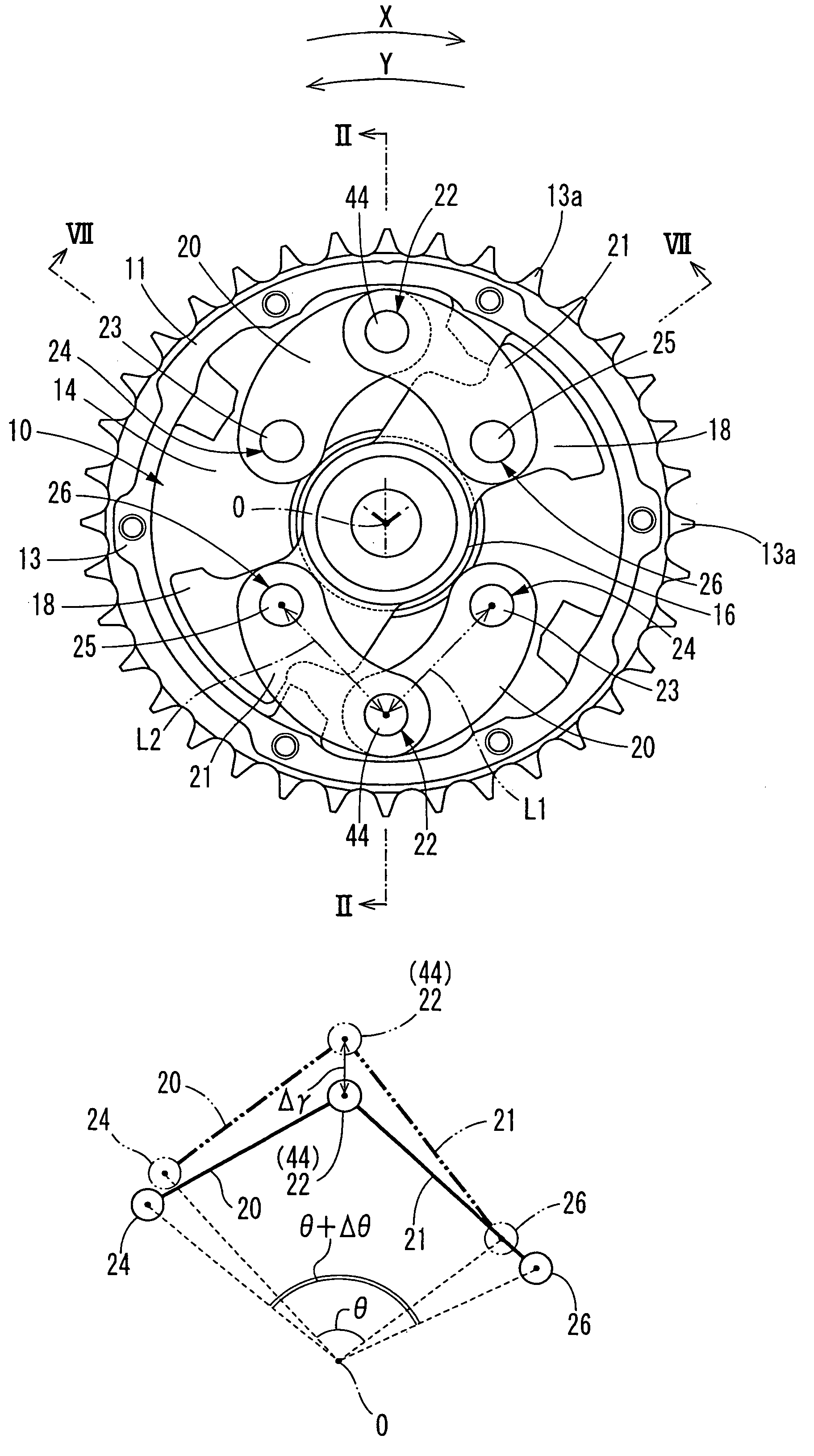
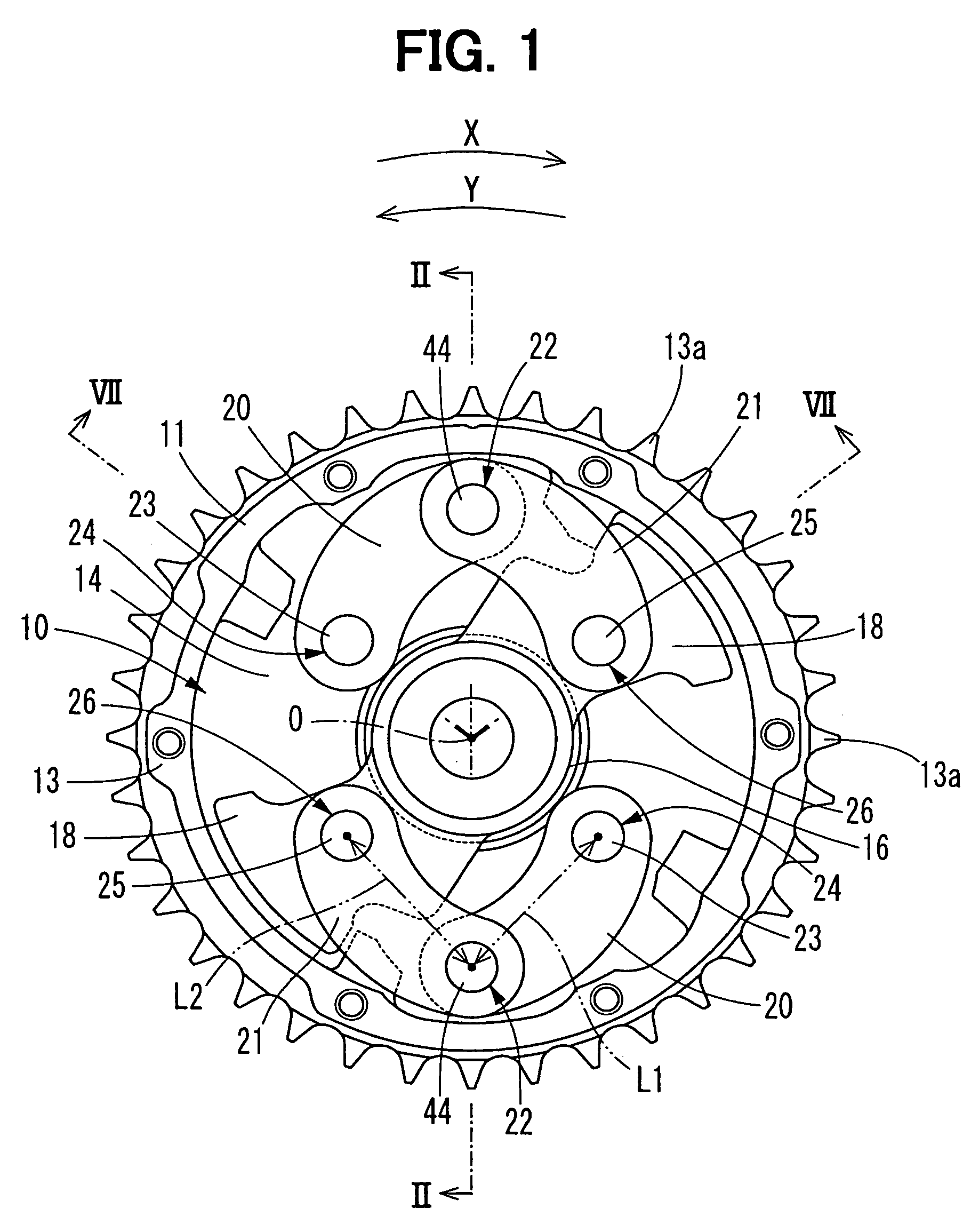
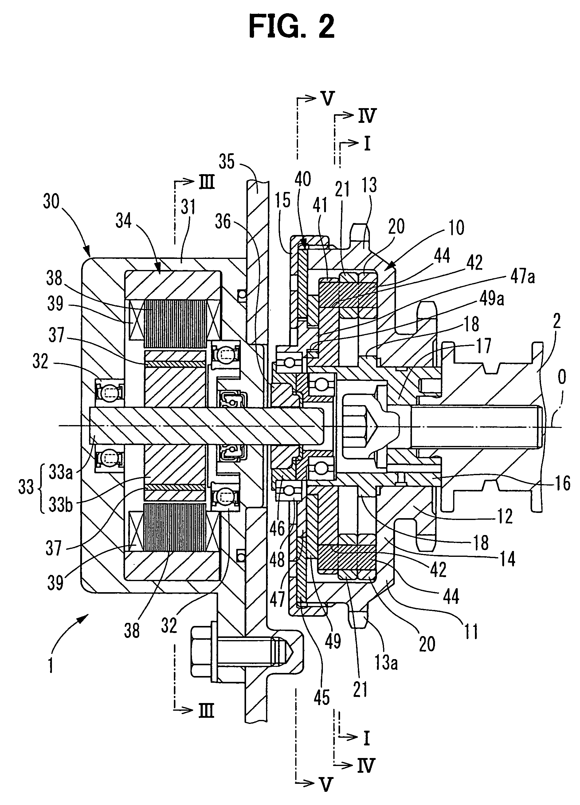
[0028]FIG. 2 shows a VVT controller 1 according to the first embodiment of the present invention. The VVT controller 1 is disposed in a torque transfer system which transfers the torque of a crankshaft (not shown) to a camshaft 2 which opens and closes at least one of an intake valve or an exhaust valve. The crankshaft is a driving shaft and the camshaft 2 is a driven shaft in this embodiment. The VVT controller 1 adjusts the valve timing of the intake valve or the exhaust valve by varying the rotational phase of the camshaft 2 relative to the crankshaft.

[0029]The VVT controller 1 has a phase adjusting mechanism 10, an electric motor 30, and a motion converting mechanism 40.

[0030]As shown in FIGS. 1 and 2, the phase adjusting mechanism 10 comprises a sprocket 11, an output shaft 16, a first arm 20, and a second arm 21 in order to adjust a relative rotational phase between the spro...


PUM


Abstract

A variable valve timing controller has a phase adjusting mechanism. The phase adjusting mechanism includes a first rotating member and second rotating member which are respectively rotate in synchronization with a driving shaft and a driven shaft of an engine, a first arm rotatably connected with the first rotating member, and a second arm rotatably connected with the second rotating member and the first arm. In the first arm, a distance between connecting points is defined as a distance L1. In the second arm, a distance between connecting points is defined as a distance L2. A ratio L1 / L2 is defined within a range of 0.5 to 2.

Description

CROSS REFERENCE TO RELATED APPLICATIONS[0001]This application is based on Japanese Patent Application No. 2005-018546 filed on Jan. 26, 2005, the disclosure of which is incorporated herein by reference.FIELD OF THE INVENTION[0002]The present invention relates to a variable valve timing controller which changes opening and closing timing of intake valves and / or exhaust valves of an internal combustion engine according to operating condition of the engine. The opening and closing timing is referred to as valve timing, the variable valve timing controller is referred to as the VVT controller, and the internal combustion engine is referred to as an engine hereinafter.BACKGROUND OF THE INVENTION[0003]The VVT controller is disposed in a torque transfer system which transfers the torque of the driving shaft of the engine to the driven shaft which opens and closes at least one of an intake valve or an exhaust valve. The VVT controller adjusts the valve timing of the valves by varying a rota...

Claims


Application Information

Patent Timeline
Patent Type & Authority Patents(United States)
IPC IPC(8): F01L1/34
CPCF01L1/022F01L1/352F01L1/024F01L2820/032F01L2101/00F01L2301/00
Inventor SUGIURA, TAEI
Owner TOYOTA JIDOSHA KK
Why Eureka
Try Eureka