

Shield connector
a shield connector and connector technology, applied in the direction of cable junctions, securing/insulating coupling contact members, coupling device connections, etc., can solve the problem of impairing the resin cover of the edge insulating, and achieve the effect of high degree of freedom of wiring path
- Summary
- Abstract
- Description
- Claims
- Application Information
AI Technical Summary
Benefits of technology
Problems solved by technology
Method used
Image

Examples
embodiment 1
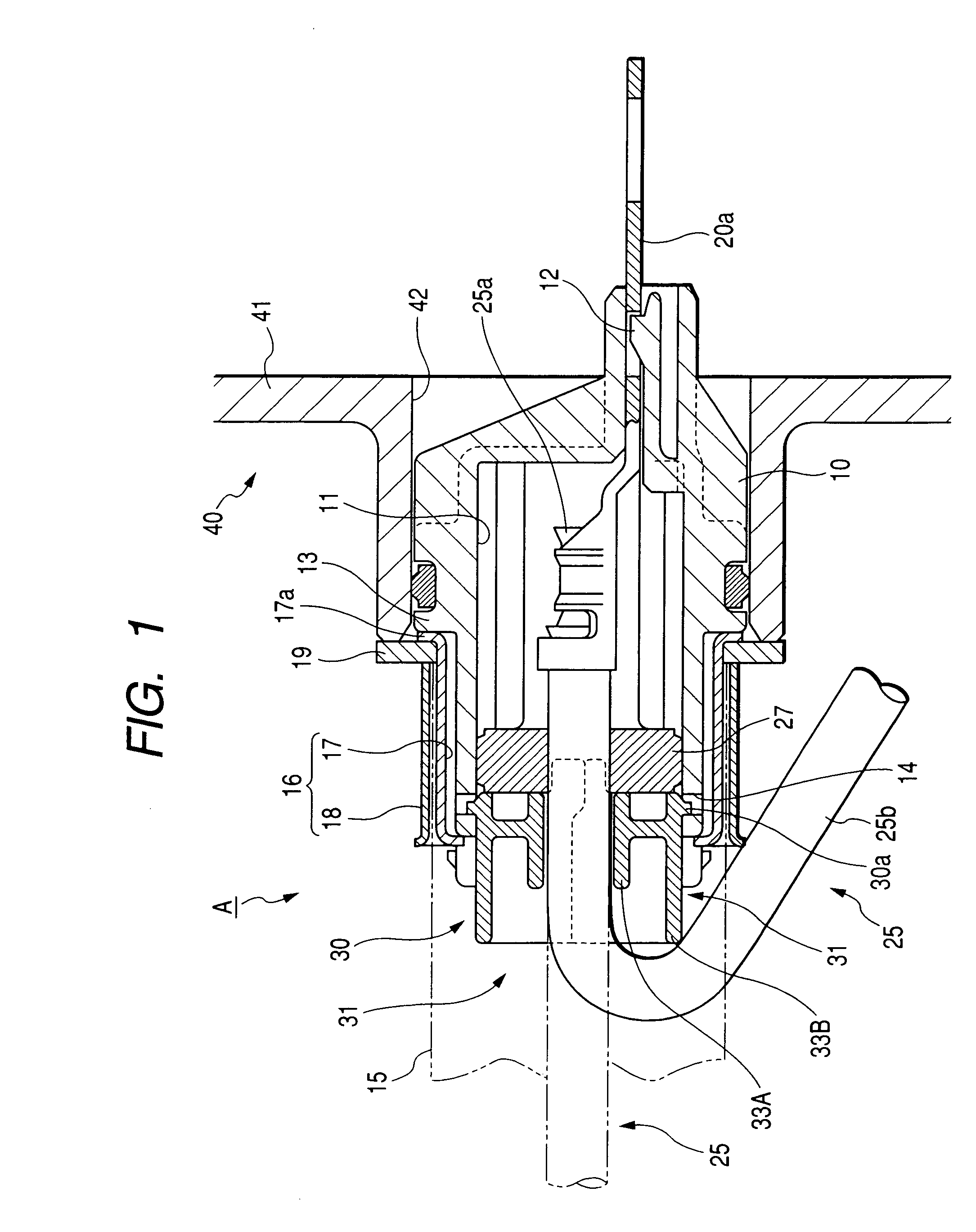
[0035]An explanation will be given of Embodiment 1 embodying the invention in reference to FIG. 1 through FIG. 5 and FIG. 10 as follows.
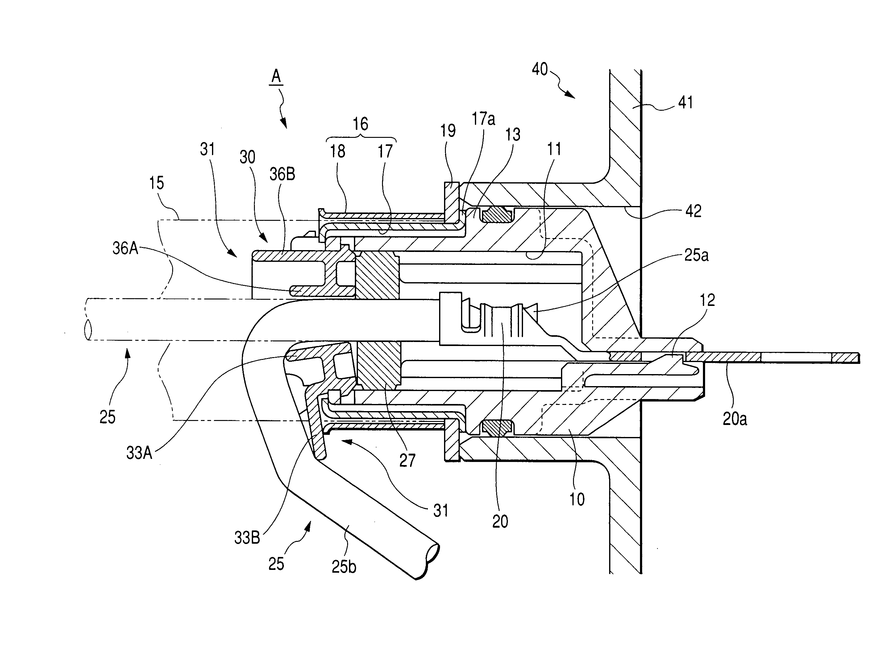
[0036]A shield connector A according to the embodiment is provided with a housing 10 made of a synthetic resin, and three (although according to the embodiment, three, may be two or four or more) of terminal metal pieces 20. Inside of the housing 10 is formed with three cavities 11 having a circular section penetrated in a front and rear direction to align by a constant pitch in a left and right direction (horizontal direction). The terminal metal pieces 20 are respectively inserted into the respective cavities 11 from a rear side and prevented from being drawn out by lances 12.
[0037]A rear end portion of the terminal metal piece 20 is connected with an electric wire 25 configured by surrounding an outer periphery of a core wire 25a by an insulating resin cover 25b by being brought into press contact therewith. An outer periphery of the resin cover ...
embodiment 2
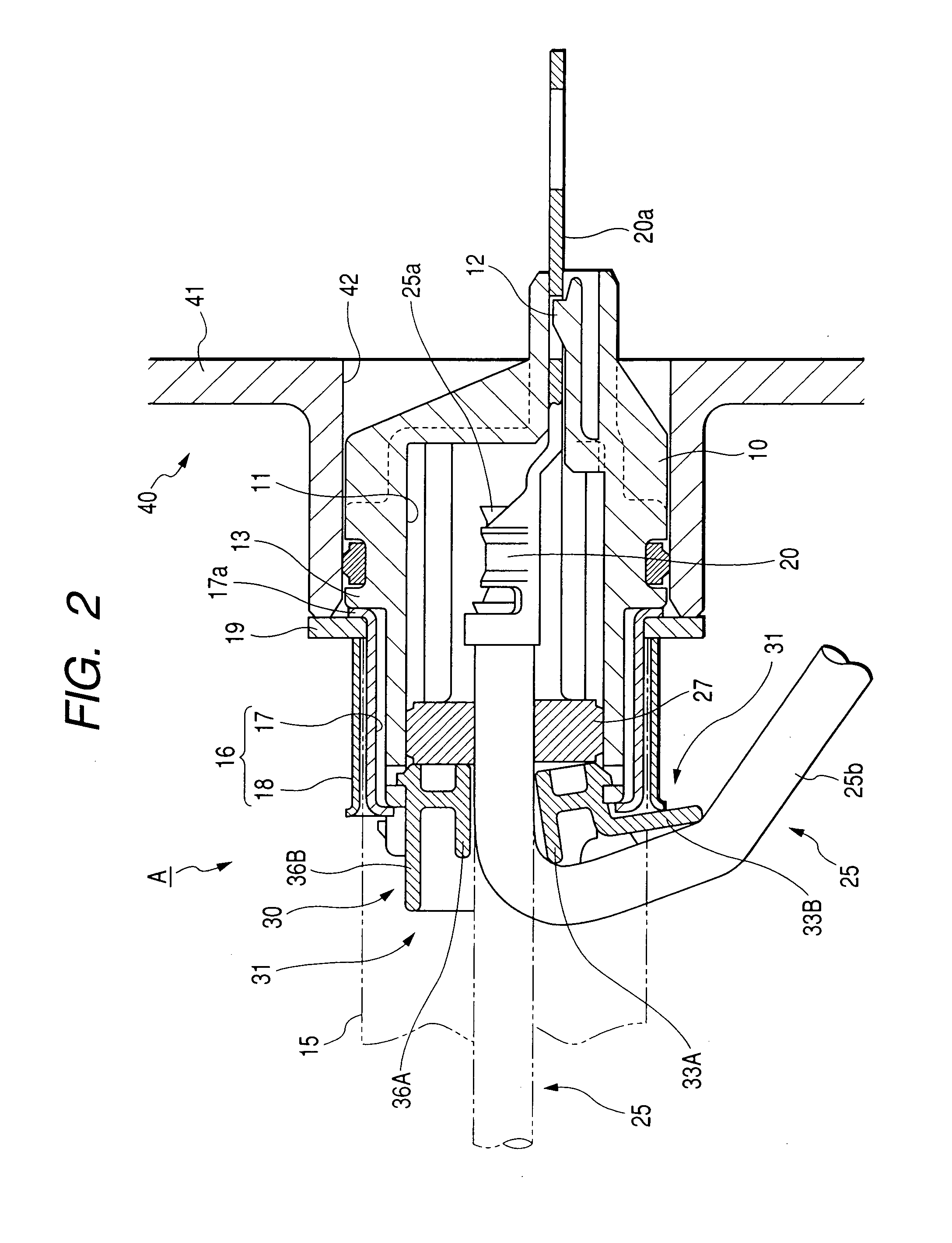
[0057]An explanation will be given of Embodiment 2 embodying the invention in reference to FIG. 6 through FIG. 10 as follows.
[0058]A shield connector A according to the embodiment is provided with a housing 10 made of a synthetic resin, and three (although according to the embodiment, three, may be two or four or more) of terminal metal pieces 20. Inside of the housing 10 is formed with three cavities 11 having a circular section penetrated in a front and rear direction to align by a constant pitch in a left and right direction (horizontal direction). The terminal metal pieces 20 are respectively inserted into the respective cavities 11 from a rear side and prevented from being drawn out by lances 12.
[0059]A rear end portion of the terminal metal piece 20 is connected with an electric wire 25 configured by surrounding an outer periphery of a core wire 25a by an insulating resin cover 25b by being brought into press contact therewith. An outer periphery of the resin cover 25b of the ...
PUM
 Abstract
Description
Claims
Application Information