Electrical power breaker with a switching contact arrangement having a current loop

Inactive Publication Date: 2006-09-05
SIEMENS AG
View PDF7 Cites 0 Cited by
  • Summary
  • Abstract
  • Description
  • Claims
  • Application Information

AI Technical Summary

Benefits of technology

[0008]The arched and concentric configuration indicates that the elementary force vectors, which together produce the torque acting on the contact lever, cooperate with the same lever arm. This occurs whilst, when the sections forming the current loop are arranged parallel to one

Problems solved by technology

A prerequisite for this so-called selective response is that the contact members remain closed until the current is at its peak, since otherwise premature erosion of the contact members and other severe damage may occu

Method used


Image

  • Electrical power breaker with a switching contact arrangement having a current loop
  • Electrical power breaker with a switching contact arrangement having a current loop
  • Electrical power breaker with a switching contact arrangement having a current loop

Examples


Example

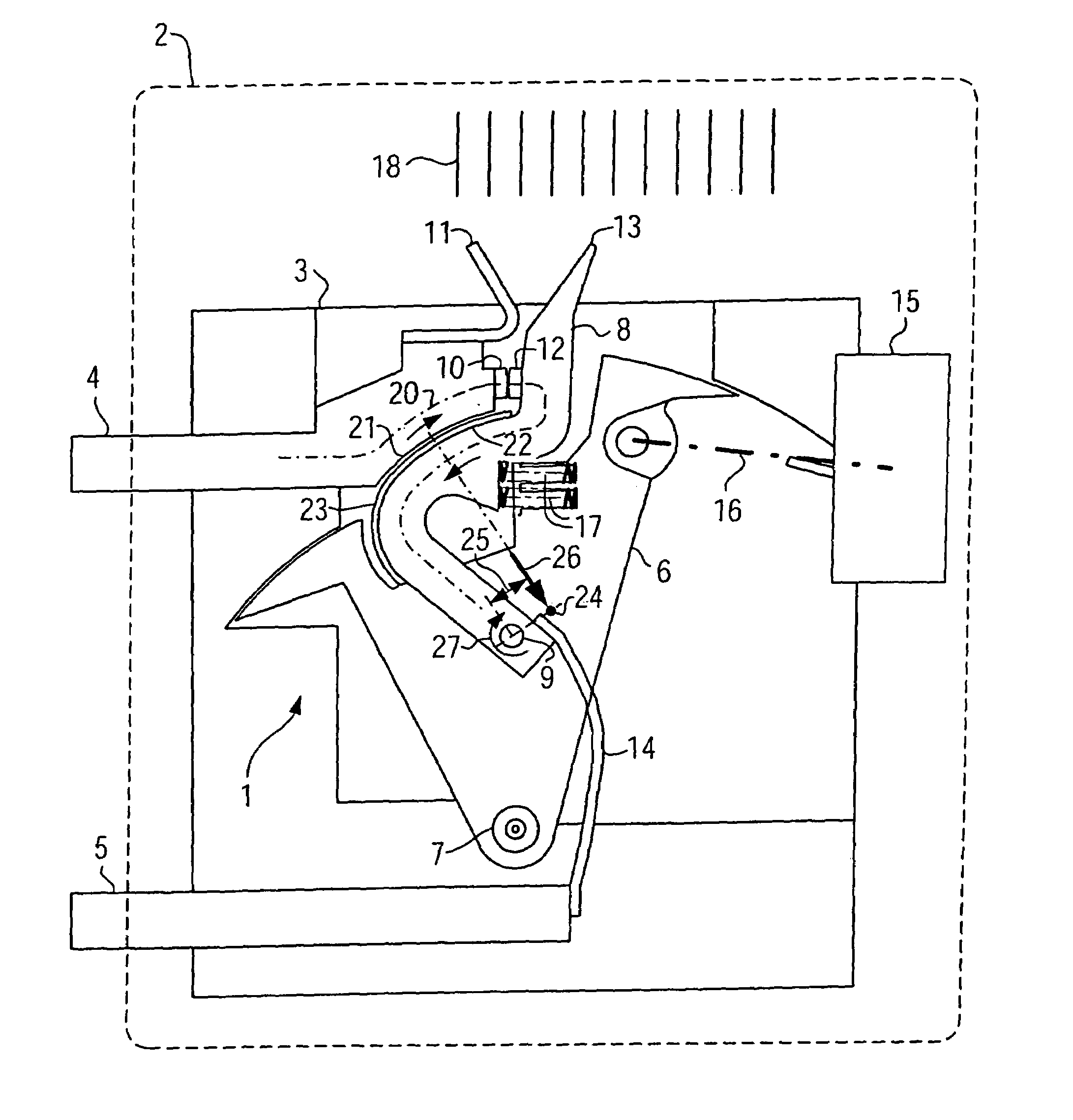
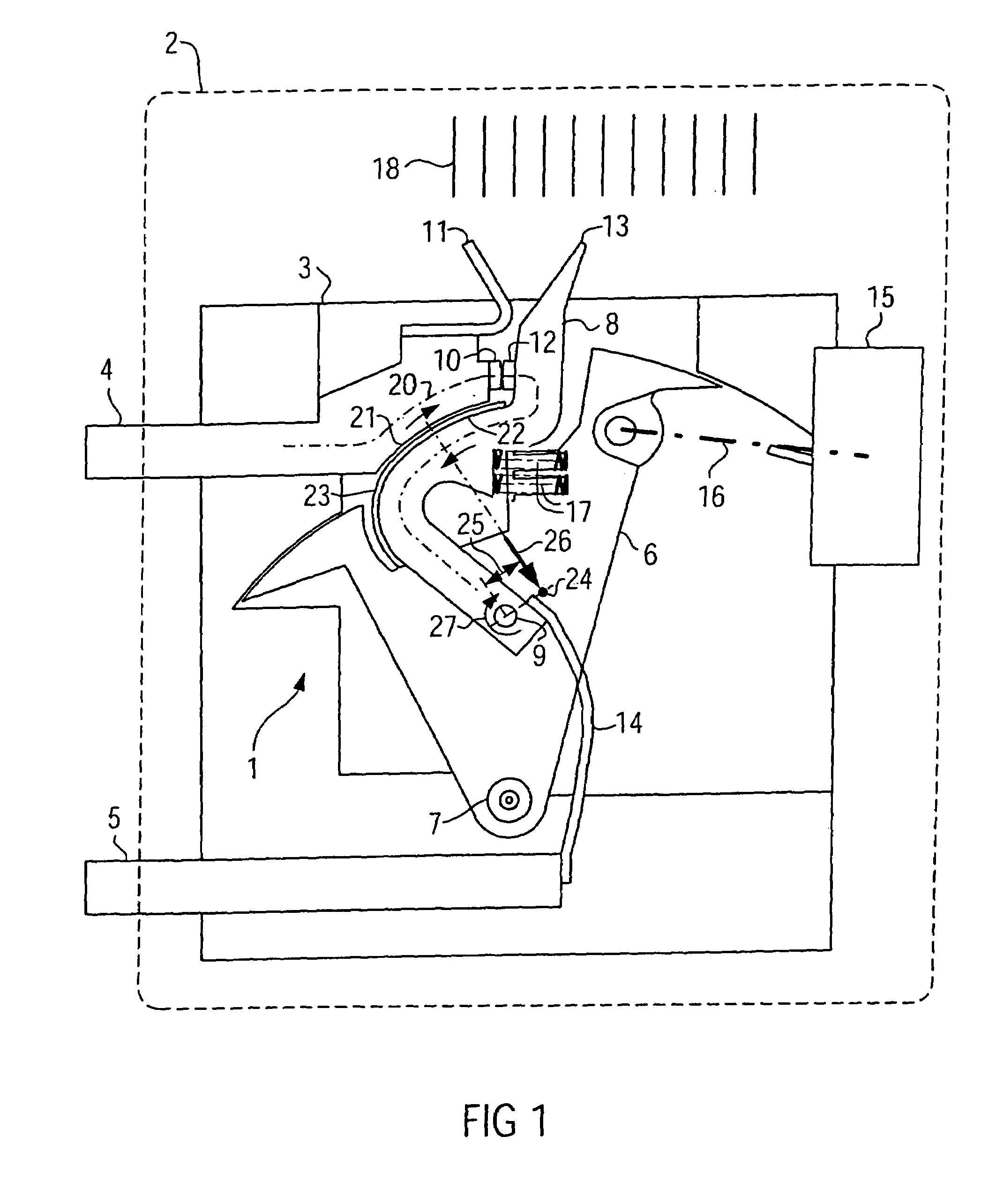
[0014]FIG. 1 shows a switching contact arrangement 1 of a low-voltage power breaker 2, indicated by dashed lines. The switching contact arrangement 1 includes a support or enclosure 3, in which an upper current conductor 4 and a lower current conductor 5 are firmly supported. Further, a contact carrier 6 is mounted such that it can move about a pivot bearing 7, close to the lower current conductor 5. A contact lever 8 is arranged on the contact carrier 6 likewise so that it can move by way of a pivot bearing 9. On its end side situated within the enclosure 3, the current conductor 4 has a stationary contact member 10 and an arcing horn 11. A moveable contact member 12, which is mounted on the contact lever 8 which is likewise provided with an arcing horn 13, cooperates with the stationary contact member 10. A flexible conductor 14 (conductor ribbon, litz wire, etc.) extends between the contact lever 8 and the lower current conductor 5.

[0015]A drive apparatus 15, indicated in FIG. 1,...


PUM


Abstract

A power breaker includes a switching contact arrangement having a current loop in order to allow a force dependent on the current to act on the contact members. For this purpose, sections, which are arranged parallel to one another and such that they are arched and concentric, are arranged on a stationary current conductor and on a contact lever. Depending on the position of a center of a resultant force, originating from the arched sections, in relation to a pivot bearing of the contact lever, a torque acts on the contact lever causing the switching contact arrangement to open or close. Using largely identical parts, power breakers which have a current-limiting or contact-force-increasing action can thus be produced.

Description

[0001]The present application hereby claims priority under 35 U.S.C. §119 on German patent application number DE 10230085.2 filed Jun. 27, 2002, the entire contents of which are hereby incorporated herein by reference.FIELD OF THE INVENTION[0002]The invention generally relates to an electrical power breaker with a switching contact arrangement. Preferably, it relates to one which includes a current conductor, carrying a stationary contact member, and a contact lever, carrying a moveable contact member. The contact lever may be arranged on a contact carrier, which can pivot in order to close and open the switching contact arrangement, such that it can move about a pivot bearing. The current conductor and the contact lever may lye opposite one another when the switching contact arrangement is closed, so as to form a current loop which generates a torque acting on the contact lever.BACKGROUND OF THE INVENTION[0003]A power breaker has been disclosed, for example, by EP 0 006 637. It is ...

Claims


Application Information

Patent Timeline
IPC IPC(8): H01H75/00H01H1/54H01H11/00H01H77/10
CPCH01H1/54H01H77/107H01H11/0006
Inventor GODESA, LUDVIK
Owner SIEMENS AG
Why Eureka
Try Eureka