Waveguide type optical splitter and waveguide type optical module comprising the same
a technology of optical splitter and optical module, which is applied in the direction of optical waveguide light guide, instruments, optics, etc., can solve the problems of inability to meet customers' needs, increase insertion loss, and light power varies according to the position of branched light signals, so as to reduce insertion loss, improve insertion loss, and reduce transmission loss
- Summary
- Abstract
- Description
- Claims
- Application Information
AI Technical Summary
Benefits of technology
Problems solved by technology
Method used
Image

Examples
first embodiment
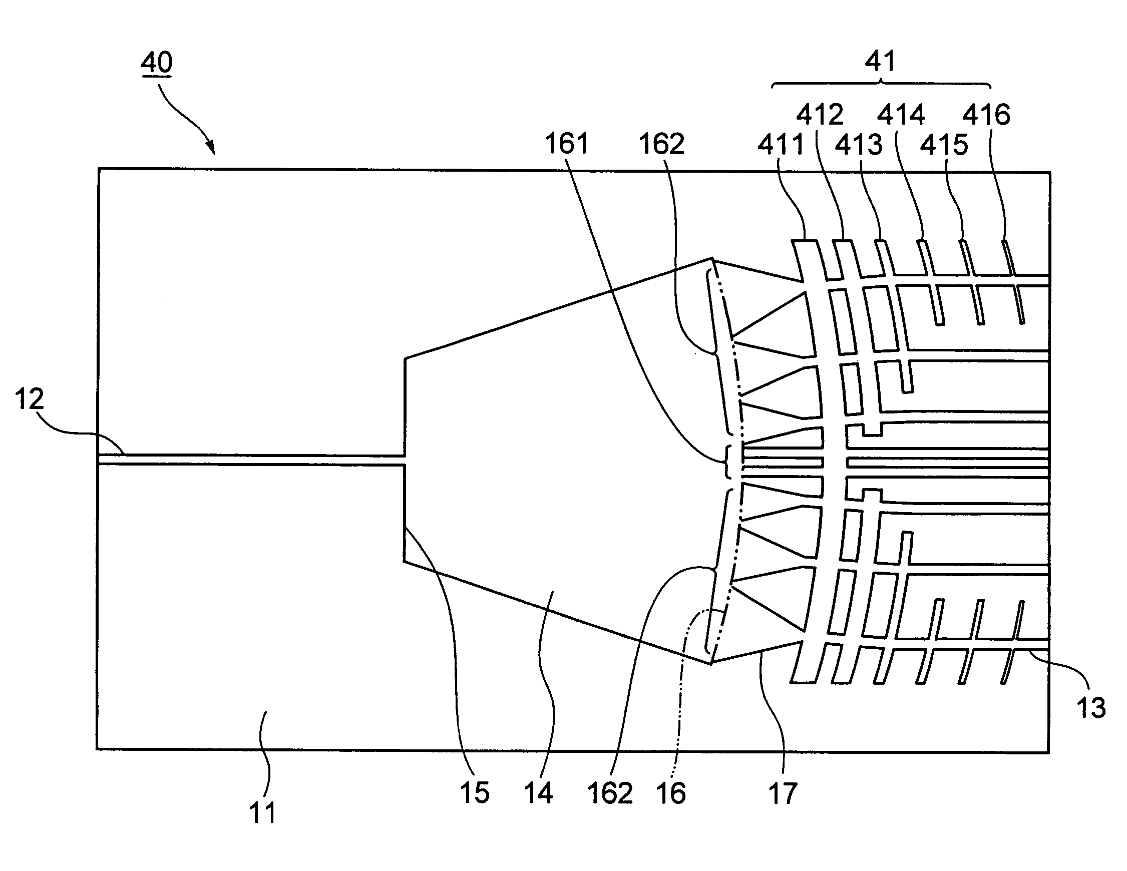
[0044]FIG. 3 is a plan view for showing a waveguide type optical splitter according to the present invention. FIG. 4 is a fragmentary enlarged view of FIG. 3. Description will be provided hereinafter by referring to FIG. 3 and FIG. 4.
[0045]In a waveguide type optical splitter 10 of the embodiment, formed on a substrate 11 are an input waveguide 12, a plurality of output waveguides 13, and a slab waveguide 14 which multi-branches the light from the input waveguide 12 into a plurality of the output waveguides 13. The slab waveguide 14 comprises an input end 15 coupled to the input waveguide 12 and an output end 16 to which a plurality of the output waveguides 13 are coupled. A plurality of the output waveguides 13 are disposed in parallel on the output side of the slab waveguide 14.
[0046]The output end 16 of the slab waveguide 14 is formed in an arc shape with the input end 15 or the vicinity being the center, and a plurality of the output waveguides 13 are connected to the arc-shape ...
second embodiment
[0060]FIG. 5[1] is a fragmentary plan view for showing the waveguide optical splitter according to the present invention. However, description will be provided hereinafter by referring to FIG. 5[1]. Descriptions of the same components as those of FIG. 3 are omitted by applying the same reference numerals or by omitting illustrations.
[0061]In FIG. 5[1], although the output end 16 is illustrated linearly, it is formed in an arc shape as shown in FIG. 3 and FIG. 4.
[0062]In the embodiment shown in FIG. 5[1], the region of the arc-shape output end 16 of the slab waveguide 14 is divided into three regions of the center portion 161, the middle portion 163, and the peripheral portion 162 along the arc and the output waveguides 13 are coupled to the slab waveguide 14. It will be described more specifically in the followings.
[0063]As shown in FIG. 5 [1], a tapered waveguide 18 is provided to the end of the output waveguide 13 which is coupled to the center portion 161 of the output end 16. Th...
third embodiment
[0069]FIG. 5[2] is a fragmentary plan view for showing the waveguide type optical splitter according to the present invention. Description will be provided hereinafter by referring to FIG. 5[2]. However, descriptions of the same components as those of FIG. 3 are omitted by applying the same reference numerals or by omitting illustrations.
[0070]The embodiment regards to a tapered waveguide 19 inserted between the slab waveguide 14 and the output waveguide 13. As for the tapered waveguide 17 of the above-described embodiment, as shown by an alternate two-dot chain line in FIG. 5[2], the wall face which defines the waveguide is formed linearly (tapered shape) so as to change the waveguide width. In the meantime, in the tapered waveguide 19, the wall face which defines the waveguide is formed in a curved shape so as to change the waveguide width. The inner wall of the tapered waveguide 19 is curved by projecting towards the inner side. In this case, it is desirable that the curved shape...
PUM
 Abstract
Description
Claims
Application Information
 - R&D Engineer
- R&D Manager
- IP Professional
- Industry Leading Data Capabilities
- Powerful AI technology
- Patent DNA Extraction
Browse by: Latest US Patents, China's latest patents, Technical Efficacy Thesaurus, Application Domain, Technology Topic.
© 2024 PatSnap. All rights reserved.Legal|Privacy policy|Modern Slavery Act Transparency Statement|Sitemap