Pipe beveling tool and method

a technology of beveling tool and pipe, which is applied in the direction of manufacturing tools, tube shearing machines, portable lathes, etc., can solve the problems of difficult to provide a relatively uniform beveled surface at the proper angle, and some difficult tasks

Inactive Publication Date: 2006-09-12
SCHEFFER DOUGLAS
View PDF17 Cites 19 Cited by
  • Summary
  • Abstract
  • Description
  • Claims
  • Application Information

AI Technical Summary

Problems solved by technology

This is a somewhat difficult task, and is particularly difficult to provide a relatively uniform beveled surface at the proper angle.

Method used


Image

  • Pipe beveling tool and method
  • Pipe beveling tool and method
  • Pipe beveling tool and method

Examples


first embodiment

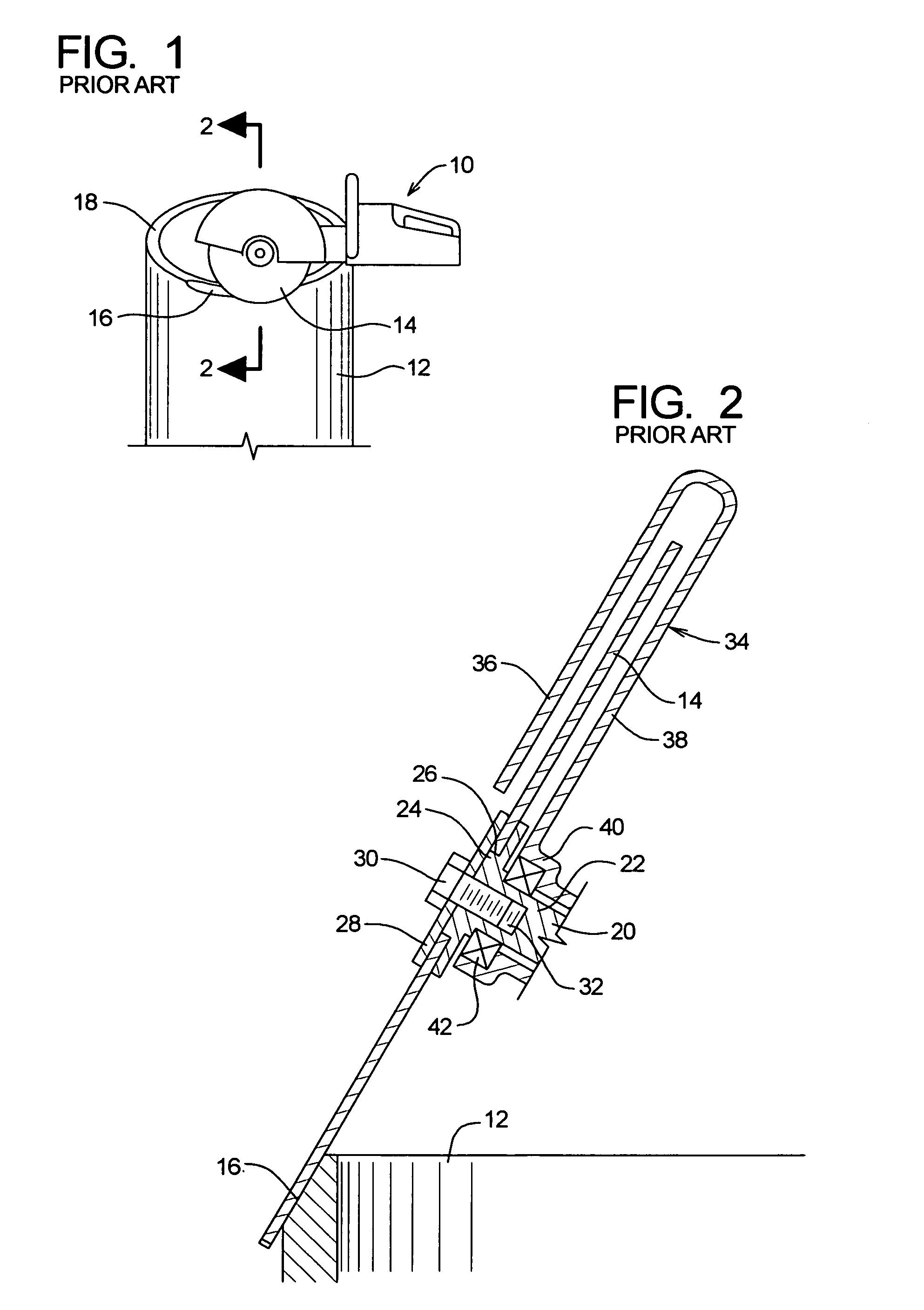
[0019]The method and apparatus of the embodiments of the present invention are able to accomplish the cutting of a pipe or the like, and also beveling an end portion of the same. A first embodiment comprises a rotary power saw section and also a bevel section.

[0020]The rotary section comprises a rear handle grip portion which is adapted to be manually grasped, and a forward saw portion having a saw mounting portion with a rotary drive member to which a rotary blade can be mounted. The rotary drive member has a transverse axis of rotation. In a configuration of the first embodiment, the rotary power saw section can be considered as having a front end, a rear end, and a front-to-rear longitudinal axis, with the transverse axis of rotation having a substantial alignment component perpendicular to the longitudinal axis.

[0021]The bevel section comprises a mounting portion and a bevel cutting portion. The mounting section is arranged to be connected to the rotary drive member so as to be ...

second embodiment

[0057]the present invention shows FIGS. 6–9. Components of the second embodiment which are the same as, or similar to, components of the first embodiment will be given like numerical designations, with an “a” suffix distinguishing those of this second embodiment.

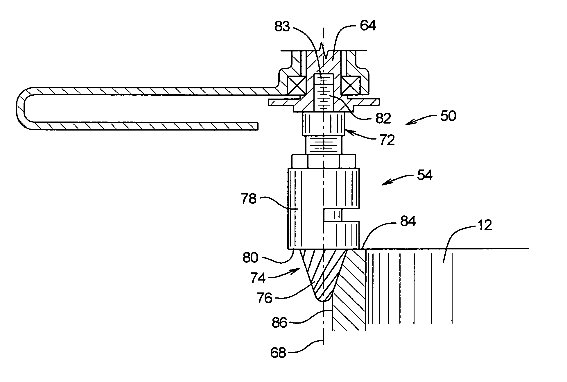
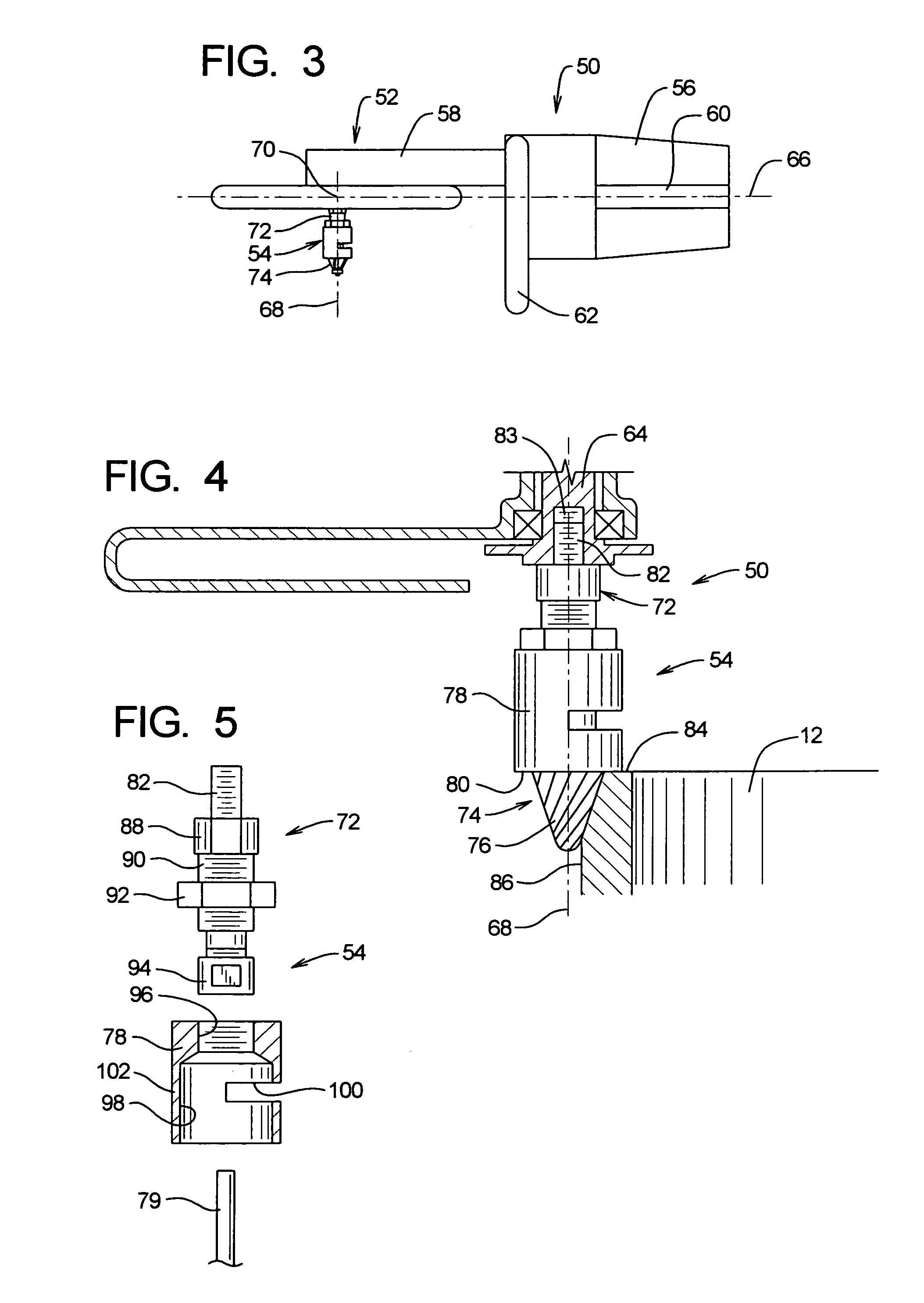
[0058]This second embodiment of the present invention is a tool assembly 50, and has the two basic sections as in the first embodiment, namely a rotary output power section 52 and a bevel section 54. The rotary output power section 52 of this second embodiment is, or may be, exactly the same as in the first embodiment, or at least similar thereto. Accordingly, this rotary output power section of the second embodiment is not shown in FIGS. 6–9.

[0059]This bevel section 54a of the second embodiment differs in some respects from the bevel section 54 of the first embodiment. It comprises a mounting section 72a and a bevel cutting section 74. The mounting section 72a has a threaded end connector 82a, the flat sided portion 88a, th...


PUM

PropertyMeasurementUnit
diameteraaaaaaaaaa
axis of rotationaaaaaaaaaa
diameteraaaaaaaaaa

Abstract

A tool assembly which is adapted to perform a cutting operation and also a beveling operation on a pipe. There is a rotary power saw which has rotary drive member to which a saw blade can be mounted. There is a bevel section having a mounting member that connects to the rotary drive member, and a bevel member. There is a locating surface portion around the axis of rotation of the bevel member, and an end lateral locating section and an apex end of the bevel member. The bevel section can be removably connected to the drive member of the power saw.

Description

CROSS-REFERENCE RELATED APPLICATIONS[0001]The present application claims the benefit of the priority of U.S. Provisional Patent Application 60 / 395,483, filed Jul. 11, 2002.BACKGROUND ART[0002]In the prior art, large plastic pipes are used to transport water or other liquids, and these can very substantially in size, with some of these being as large as one to two feet in diameter, or possibly larger. Sometimes they have to be cut to different lengths and joined end to end in some manner, and this often requires beveling the end edge portion of the pipe.[0003]One common method of cutting these pipes is to use a rotary power saw which has a rear hand grip section and a front cutting section. At the cutting section, there is a disc saw blade which is mounted about an axis of rotation that is transversely aligned relative to a forward to rear axis of the power tool. It is common practice in the industry to sometimes bevel the end to edge portion of the pipe by using the saw blade of thi...

Claims


Application Information

Patent Timeline
Patent Type & Authority Patents(United States)
IPC IPC(8): B23P23/00B23B5/16B23C3/04B23C3/18
CPCB23B5/168B23C3/122Y10T29/5199Y10T82/16967Y10T82/22Y10T29/5114Y10T83/0596
Inventor SCHEFFER, DOUGLAS
Owner SCHEFFER DOUGLAS
Why Eureka
Try Eureka