Thrust bearing and method of making same

a technology of thrust bearings and bearings, which is applied in the direction of roller bearings, mechanical equipment, transportation and packaging, etc., can solve the problems of difficult forming of staked portions b>40/b>, or similarly curled portions, and at a risk of fracturing thrust races

Inactive Publication Date: 2006-09-12
KOYO BEARINGS NORTH AMERICA LLC
View PDF29 Cites 19 Cited by
  • Summary
  • Abstract
  • Description
  • Claims
  • Application Information

AI Technical Summary

Problems solved by technology

Because of the limited ductility of the material, the forming of staked portions 40...

Method used


Image

  • Thrust bearing and method of making same
  • Thrust bearing and method of making same

Examples


Embodiment Construction

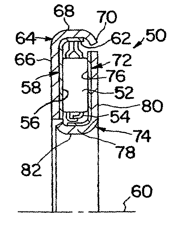
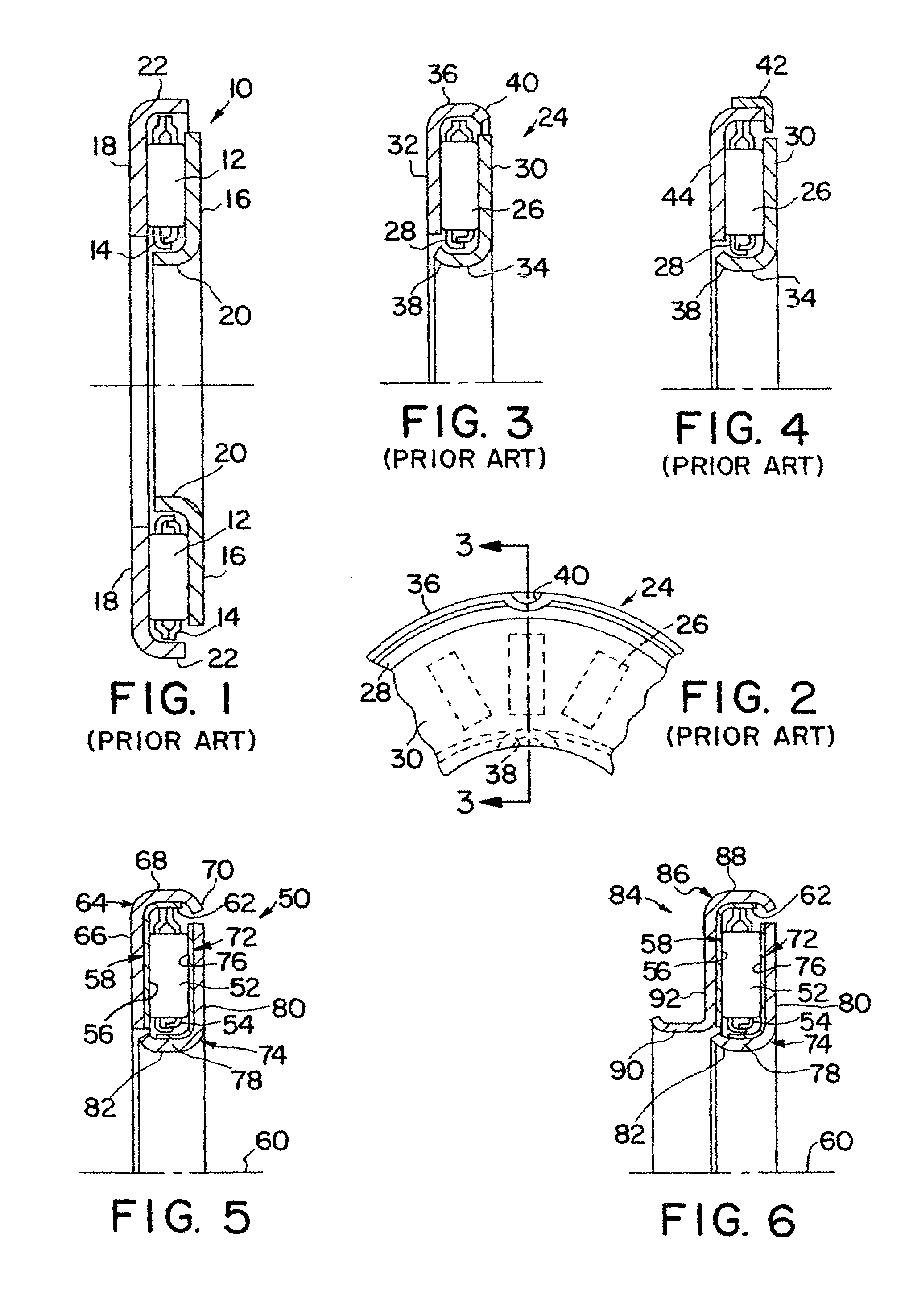
[0015]Referring now to the other drawing figures, FIG. 5 illustrates a thrust bearing 50, according to the present invention, with needle rollers 52 retained within a bearing cage 54 and in rolling contact with a flat raceway portion 56 of a first race component 58. The first race component is made of a material suitable for high quality raceways, such as, for example, high carbon steel finished to a smooth wear surface. The flat raceway portion 56 is circular, defined about an axis 60. The bearing cage 54 is engageable with an axially extending lip portion 62 of the first race component 58 that may be used for piloting of the bearing cage 54.

[0016]A second race component 64 includes a flat portion 66 in contact with the raceway portion 56 of the first race component 58 and includes a lip portion 68 that extends axially and radially from the flat portion 66 and beyond the lip portion 62 of the first race component 58 such that the second race component is engageable by the bearing c...


PUM


Abstract

A first race component includes a flat, circular raceway portion, defined about an axis, and an axially extending lip portion. A plurality of needle rollers is arranged radially with respect to the axis for rolling contact with the flat raceway. A bearing cage retains the needle rollers and is engageable with the lip portion of the first component for piloting of the bearing cage. A second race component, made of different material, includes a flat portion in contact with the raceway portion of the first race component and a lip portion extending axially and radially from the flat portion and beyond the lip portion of the first race component such that the second race component is engageable by the bearing cage to hold the first race component, the second race component and the bearing cage together as an assembly.

Description

BACKGROUND OF THE INVENTION[0001]This invention relates generally to thrust bearings and, more particularly, to thrust races used in thrust bearings with needle rollers.[0002]Thrust bearings with needle rollers are in general use in transmissions and similar devices to support axial loads between components. For example, such thrust bearings are used in automotive torque converters to position and support a stator. Examples of such thrust bearings with needle rollers are illustrated inFIGS. 1–4. FIG. 1 illustrates a thrust bearing 10 with needle rollers 12 retained within a bearing cage 14 and in rolling contact with raceways of an inner thrust race 16 and an outer thrust race 18 that include inner and outer lips 20 and 22, respectively, that may be used for piloting of the bearing cage 14.[0003]FIGS. 2 and 3 illustrate a similar thrust bearing 24 with needle rollers 26 retained within a bearing cage 28 and in rolling contact with raceways of an inner thrust race 30 and an outer thr...

Claims


Application Information

Patent Timeline
IPC IPC(8): F16C33/46B62D53/08F16C33/58F16C43/04F16C19/30F16C19/32F16C19/46F16C33/54F16C33/62
CPCF16C19/30F16C33/588F16C33/62F16C33/54F16C33/4605F16C33/547F16C33/60
Inventor SHATTUCK, CHARLES W.RICHTMEYER, ROBERT D.MURPHY, RICHARD F.
Owner KOYO BEARINGS NORTH AMERICA LLC
Why Eureka
Try Eureka