Array antenna capable of controlling antenna characteristic

a technology of antenna characteristic and array antenna, which is applied in the direction of slot antenna, electrically short antenna, antenna, etc., can solve the problems of failure to control the antenna characteristic, and achieve the effect of compact array antenna allowing electrical switching of directivity

Inactive Publication Date: 2006-09-12
ATR ADVANCED TELECOMM RES INST INT
View PDF5 Cites 162 Cited by
  • Summary
  • Abstract
  • Description
  • Claims
  • Application Information

AI Technical Summary

Benefits of technology

[0017]Another object of the present invention is to provide an array antenna having sensitivity even when it is located near a conductor and allowing electrical switching of its directivity.
[0018]Yet another object of the present invention is to provide a compact array antenna allowing electrical switching of the directivity.
[0042]Therefore, according to the present invention, the array antenna allowing electrical switching of directivity can operate even in the vicinity of a conductor such as metal.
[0044]Therefore, according to the present invention, the array antenna allowing electrical switching of directivity can be compact.

Problems solved by technology

On the other hand, once the slot line is formed in the cavity resonator, modification of a shape, a dimension, and arrangement thereof is no longer allowed, resulting in failure in controlling the antenna characteristic.

Method used


Image

  • Array antenna capable of controlling antenna characteristic
  • Array antenna capable of controlling antenna characteristic
  • Array antenna capable of controlling antenna characteristic

Examples


embodiment 1

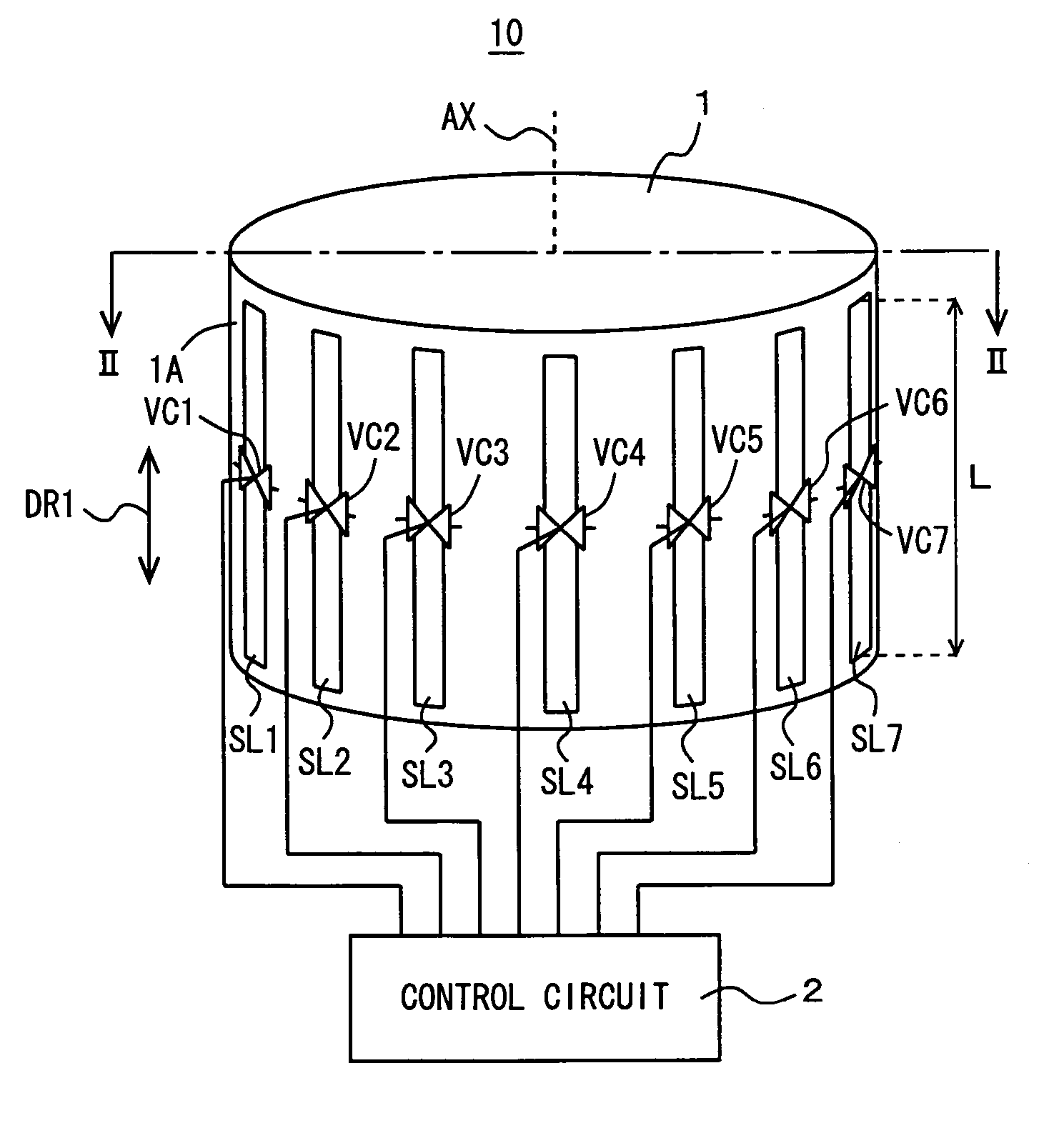
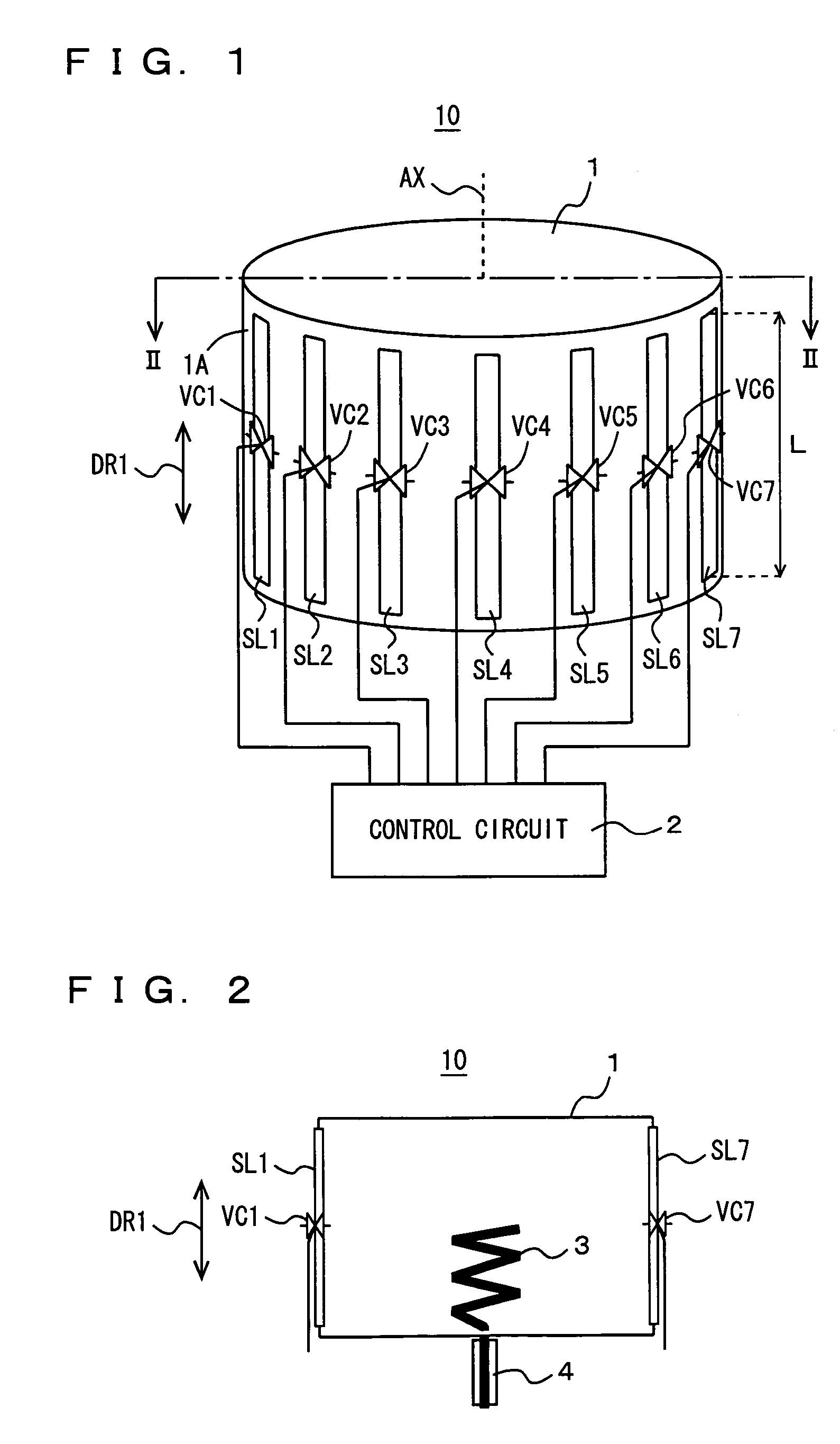
[0092]FIG. 1 is a schematic diagram of an array antenna in Embodiment 1. An array antenna 10 in Embodiment 1 includes a cavity conductor 1, a plurality of slot lines SL1 to SL7, variable capacitance elements VC1 to VC7, and a control circuit 2.

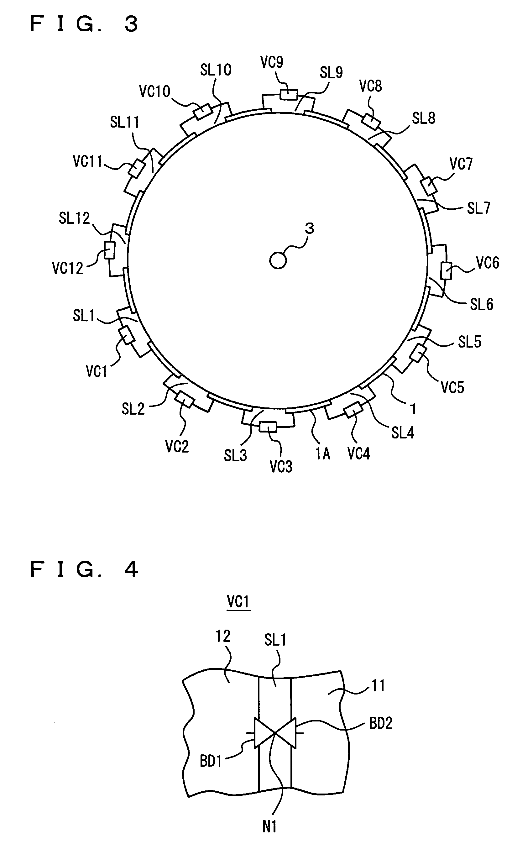
[0093]Though seven slot lines SL1 to SL7 and seven variable capacitance elements VC1 to VC7 are shown in FIG. 1, in actual, array antenna 10 includes twelve slot lines SL1 to SL12 and twelve variable capacitance elements VC1 to VC12.

[0094]Cavity conductor 1 has a substantially cylindrical shape and is made of copper (Cu). Cavity conductor 1 attains a function as a resonator or a waveguide. Each of slot lines SL1 to SL7 is provided on an outer circumferential surface 1A of cavity conductor 1 along a rotation axis direction DR1. Each of slot lines SL1 to SL7 has a length L, which is comparable to approximately λ / 2 when a radio wave transmitted / received by array antenna 10 has a wavelength λ.

[0095]Variable capacitance elements VC1 to VC7 are load...

embodiment 2

[0215]FIG. 28 is a plan view of the array antenna according to Embodiment 2, and FIG. 29 is a cross-sectional view of the array antenna along the line XXIX—XXIX shown in FIG. 28. An array antenna 110 according to Embodiment 2 includes a dielectric substrate 111, slot lines 113 to 115, a microstrip line 116, a feeder unit 117, varactor diodes 118, 119, and a directivity control unit 101.

[0216]Dielectric substrate 111 has a substantially rectangular two-dimensional shape. A conductor 112 is adhered on an entire one main surface 111A of dielectric substrate 111, and slot lines 113 to 115 are formed by removing a prescribed portion of conductor 112. Here, all of slot lines 113 to 115 have an equal length L and an equal width W, and the slot lines are provided substantially in parallel to one side of the rectangle. Slot line 114 and slot line 115 are arranged symmetrically around slot line 113. Here, an interval d between slot line 113 and slot lines 114, 115 is set, for example, to ¼ of...

embodiment 3

[0249]FIG. 39 is a plan view of an array antenna according to Embodiment 3, while FIG. 40 is a cross-sectional view of the array antenna along the line XXXX—XXXX shown in FIG. 39.

[0250]An array antenna 200 according to Embodiment 3 is obtained by replacing directivity control unit 101 of array antenna 110 shown in FIGS. 28 and 29 with a directivity control unit 210 and by adding slot lines 201, 202 and varactor diodes 203, 204. Array antenna 200 is otherwise the same as array antenna 110.

[0251]Slot lines 201, 202 have a length L and a width W the same as those of slot lines 113, 114 and 115, and slot lines 201, 202 are provided in parallel to slot lines 113, 114 and 115. Slot line 201 is arranged on the left of slot line 114, while slot line 202 is arranged on the right of slot line 115. In addition, an interval between slot line 201 and slot line 114 and an interval between slot line 202 and slot line 115 are set to interval d (=λ / 4) as described above.

[0252]Varactor diodes 203, 20...


PUM


Abstract

An array antenna includes a feeder element, a parasitic element implemented by a slot line, a variable capacitance element, and a directivity switching unit. The variable capacitance element is loaded in the slot line. The directivity switching unit supplies a control voltage to the variable capacitance element in order to vary the capacitance, and switches directivity of the array antenna.

Description

BACKGROUND OF THE INVENTION[0001]1. Field of the Invention[0002]The present invention relates to an array antenna capable of controlling an antenna characteristic.[0003]2. Description of the Background Art[0004]A conventional array antenna includes a cavity resonator, a feeder element, and a plurality of slot lines. The cavity resonator has a substantially cylindrical shape and is made of metal. The feeder element is provided in the cavity resonator. The plurality of slot lines are arranged substantially in parallel to one another on a cylinder end surface of the cavity resonator in a direction of a rotation axis of the cylindrical shape.[0005]An electromagnetic wave emitted from the feeder element by feeding electric power thereto is emitted outside the cavity resonator through the plurality of slot lines arranged on the cylinder end surface (see “Print Slot Yagi-Uda Antenna with Through-hole Cavity,” Manabu Yamamoto, Naoki Kobayashi, and Kiyohiko Itoh, Communications Society Confe...

Claims


Application Information

Patent Timeline
Patent Type & Authority Patents(United States)
IPC IPC(8): H01Q19/00H01Q9/00H01Q3/24H01Q13/10H01Q15/02H01Q15/10H01Q19/32
CPCH01Q3/242H01Q13/10H01Q19/32H01Q15/10H01Q15/02
Inventor IIGUSA, KYOICHISAWAYA, TAKUMAOHIRA, TAKASHITANAKA, HIROKI
Owner ATR ADVANCED TELECOMM RES INST INT
Why Eureka
Try Eureka