

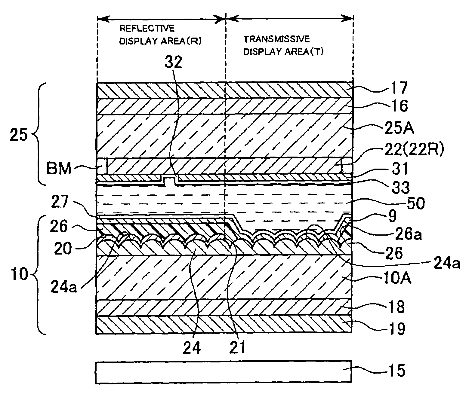
Transflective liquid crystal display device having surface roughness in the transmissive area and homeotropic alignment
a liquid crystal display and transflective technology, applied in non-linear optics, instruments, optics, etc., can solve the problems of deteriorating display properties and increasing costs, and achieve the effect of reducing or preventing display defects
- Summary
- Abstract
- Description
- Claims
- Application Information
AI Technical Summary
Benefits of technology
Problems solved by technology
Method used
Image

Examples
first exemplary embodiment
[0042
[0043]A first exemplary embodiment of the present invention will now be described with reference to the figures.
[0044]The first exemplary embodiment is an active-matrix liquid crystal display device employing thin film transistors (referred to as TFTs hereinafter) as switching elements.
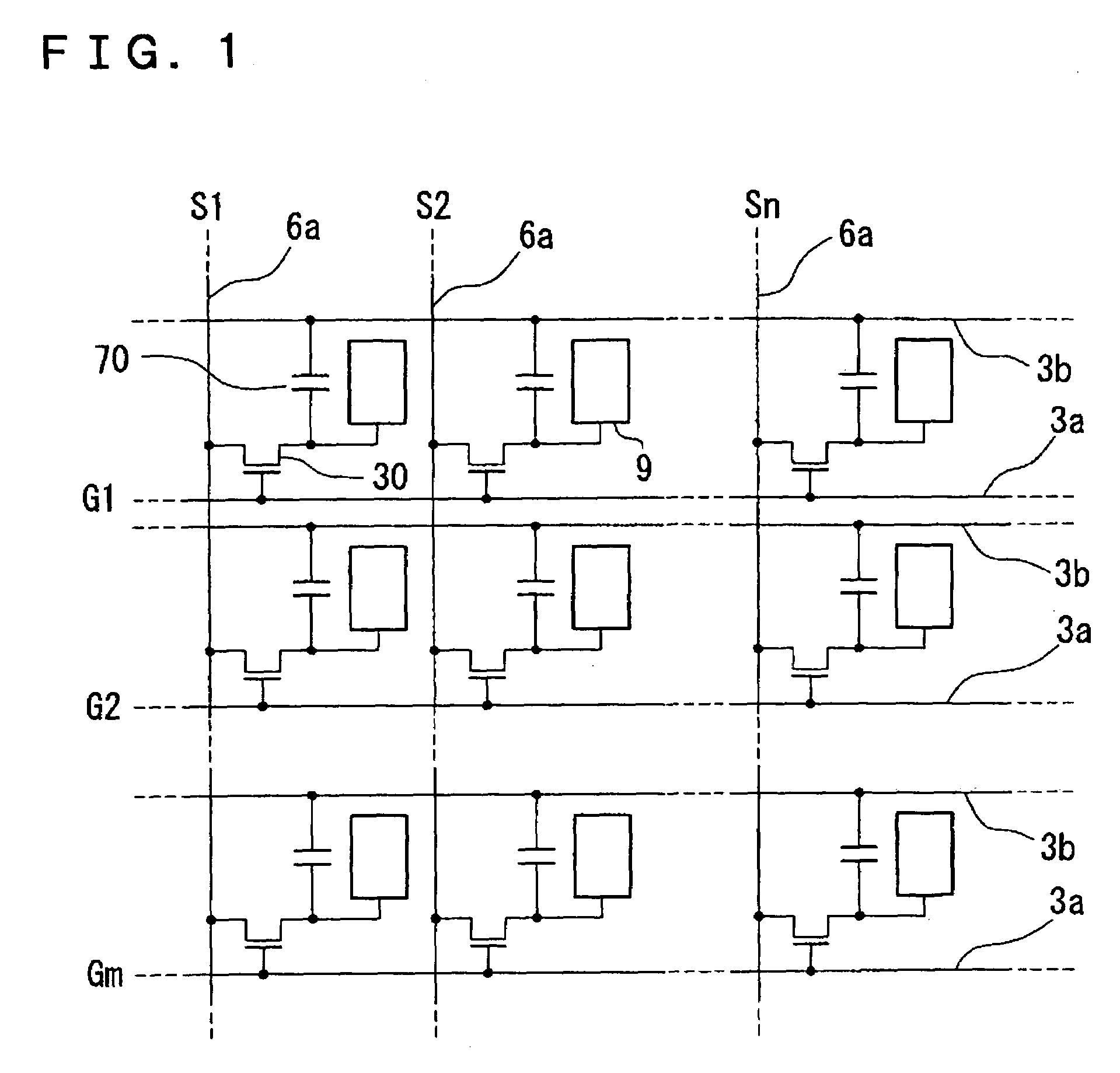
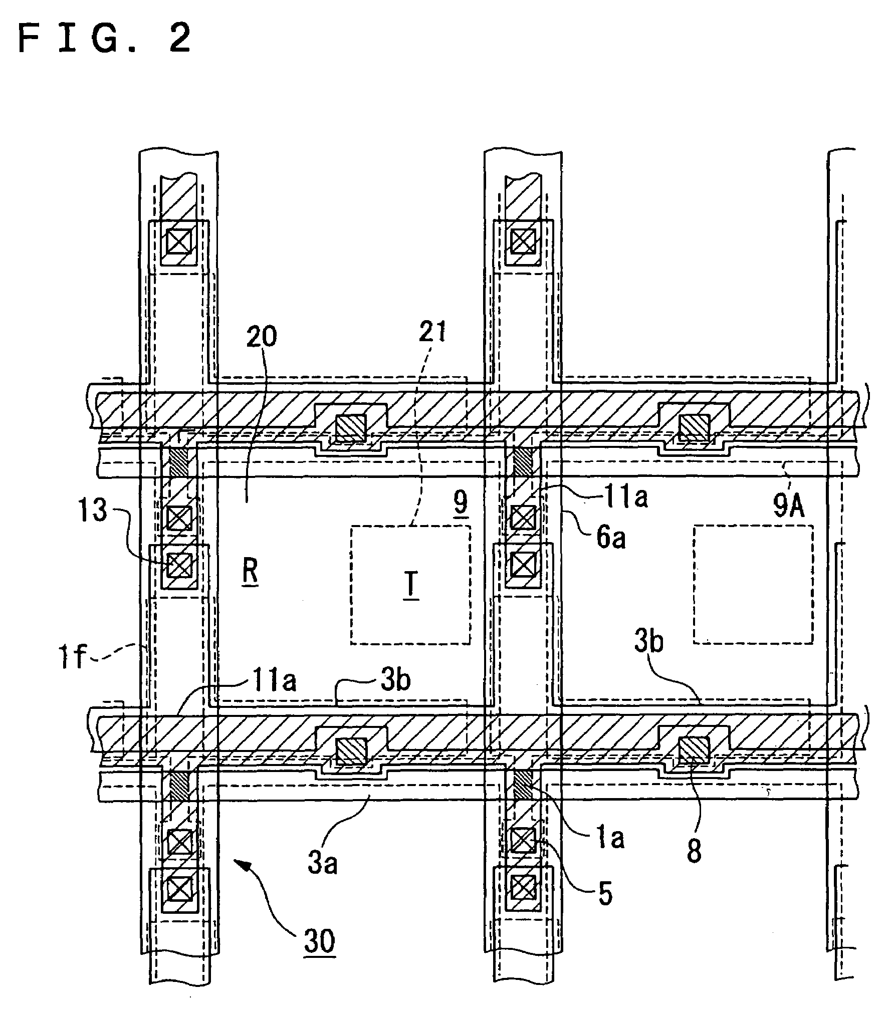
[0045]FIG. 1 illustrates an equivalent circuit schematic having a plurality of dots arranged in a matrix forming an image display region of the liquid crystal display device according to the first exemplary embodiment. FIG. 2 is a plan view of the dots disposed adjacent to one another on a TFT-array substrate. FIG. 3 includes a plan view (upper half of the figure) and a cross-sectional view (lower half of the figure) of the liquid crystal display device. In each of the figures, each layer and component is shown at a different scale to improve viewability.
[0046]Referring to FIG. 1, in the liquid crystal display device of the first exemplary embodiment, the plurality of dots arranged in a matrix fo...
second exemplary embodiment
[0069
[0070]A second exemplary embodiment of the present invention will now be described with reference to the figures.
[0071]FIG. 4 includes a schematic plan view and cross-sectional view of a liquid crystal display device according to the second exemplary embodiment, and corresponds to FIG. 3 of the first exemplary embodiment. The basic structure of the liquid crystal display device of the second exemplary embodiment is equivalent to that of the first exemplary embodiment, but has a different configuration to form the irregularities. Accordingly, components in FIG. 4, similar to those in FIG. 3, are indicated by the same reference numerals, and the detailed descriptions of those components will be omitted.
[0072]As is shown in FIG. 4, instead of having the insulation film 24 as in FIG. 3, each dot region of the second exemplary embodiment has irregularities 28 on the surface of the main substrate body 10A adjacent to the liquid crystal layer 50 to form irregularities for diffusion in...
third exemplary embodiment
[0076
[0077]A third exemplary embodiment of the present invention will now be described with reference to FIG. 5.
[0078]FIG. 5 includes a schematic plan view and cross-sectional view of a liquid crystal display device according to the third exemplary embodiment, and corresponds to FIG. 3 of the first exemplary embodiment. The basic structure of the liquid crystal display device of the third exemplary embodiment is equivalent to that of the first exemplary embodiment, but is different from the first exemplary embodiment of FIG. 3 in that the color-filter layer 22 is disposed adjacent to the TFT-array substrate 10. Accordingly, components in FIG. 5 similar to those in FIG. 3 are indicated by the same reference numerals, and the detailed descriptions of those components will be omitted.
[0079]In each dot region of the third exemplary embodiment, the insulation film 24 having the irregularities 24a, the reflective film 20, and the color-filter layer 22 are disposed over the reflective disp...
PUM
| Property | Measurement | Unit |
|---|---|---|
| height | aaaaa | aaaaa |
| angle | aaaaa | aaaaa |
| height | aaaaa | aaaaa |
Abstract
Description
Claims
Application Information