
Earplug

a technology of earplugs and ear canals, which is applied in the field of earplugs, can solve the problems of excessive pressure being brought to the walls of the ear canal, the type of earplugs that are disclosed above, and the discomfort of a significant proportion of the wearer population, so as to achieve a high degree of comfort and attenuation of exterior noise. , the effect of deep and easy insertion into the ear

Active Publication Date: 2006-09-19
MOLDEXMETRIC
View PDF10 Cites 55 Cited by
  • Summary
  • Abstract
  • Description
  • Claims
  • Application Information

AI Technical Summary

Benefits of technology

The design ensures comfortable and effective noise attenuation with easy insertion and removal, eliminating the need for a separate two-piece construction and associated increased costs.

Problems solved by technology

The prior art earplugs of the type disclosed above typically have a number of problems.
For example, the earplug shown in U.S. Pat. No. 4,867,149 has a solid shaft member to support the multiple flanges and this type of earplug can create discomfort in a significant proportion of the wearer population.
This discomfort would generally be perceived as a sense of excessive pressure being brought to bear on the walls of the ear canal because of the central solid shaft member not flexing adequately to the curvature of the car canal.
However, since the product made in accordance with the U.S. Pat. No. Des. 253,723 is of a softer material, it is difficult to insert this earplug fully into the ear since the rear end of the earplug does not have sufficient stiffness for the user to fully insert the earplug into the ear.
This two-piece construction increases the cost of the earplug since the separate pieces must be separately injection molded and must then be assembled to form the earplug.
The combination of the two materials requires additional labor and handling in manufacturing and thereby increases the cost relative to a one-piece earplug injection molded out of a single material.

Method used


Image

  • Earplug
  • Earplug
  • Earplug

Examples


Embodiment Construction

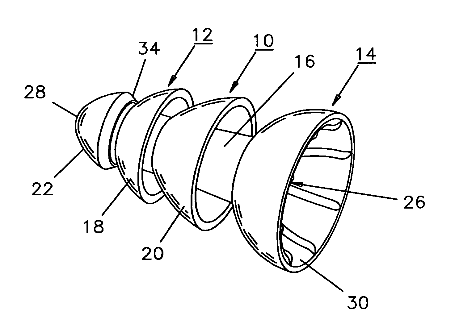
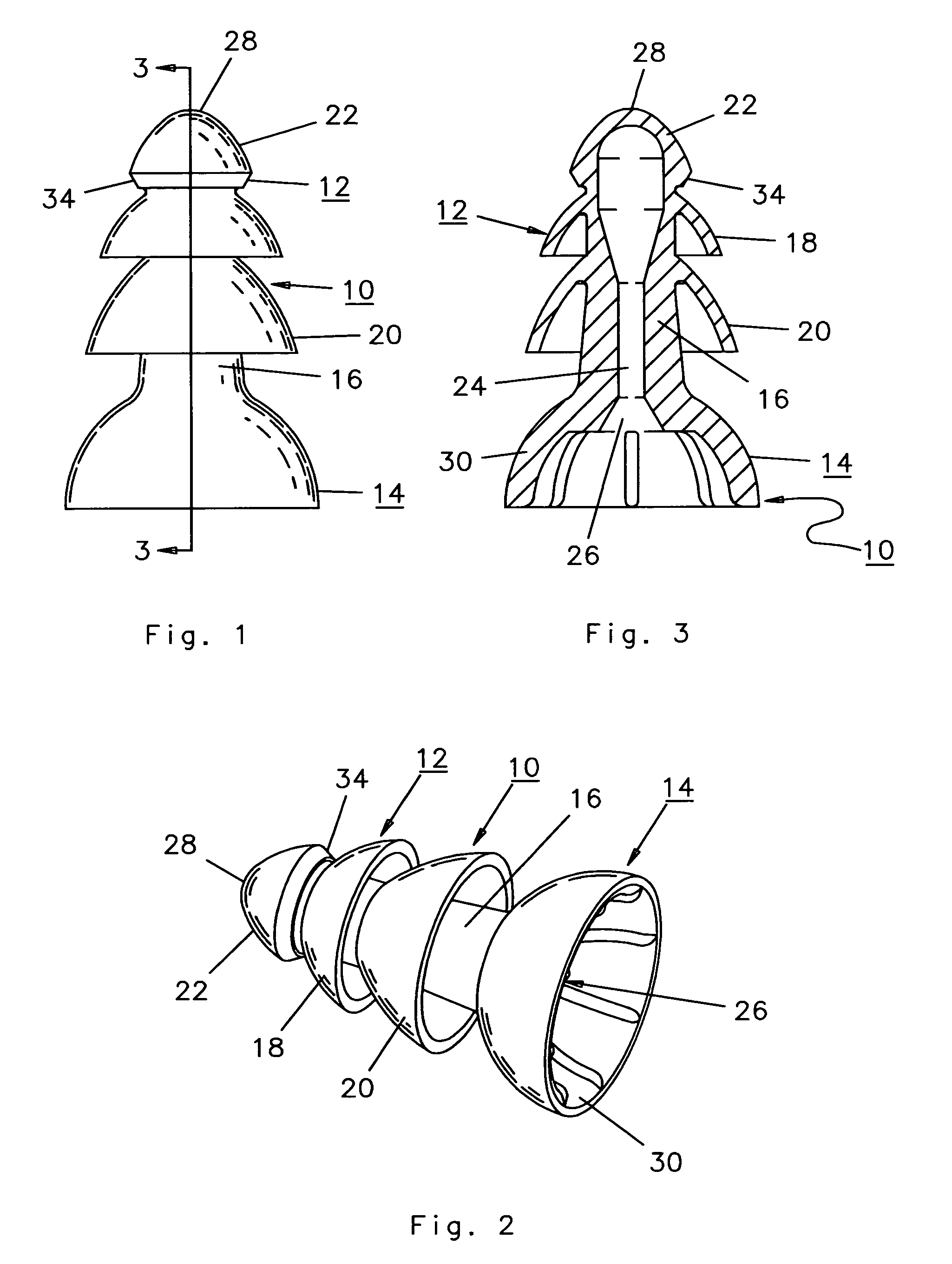
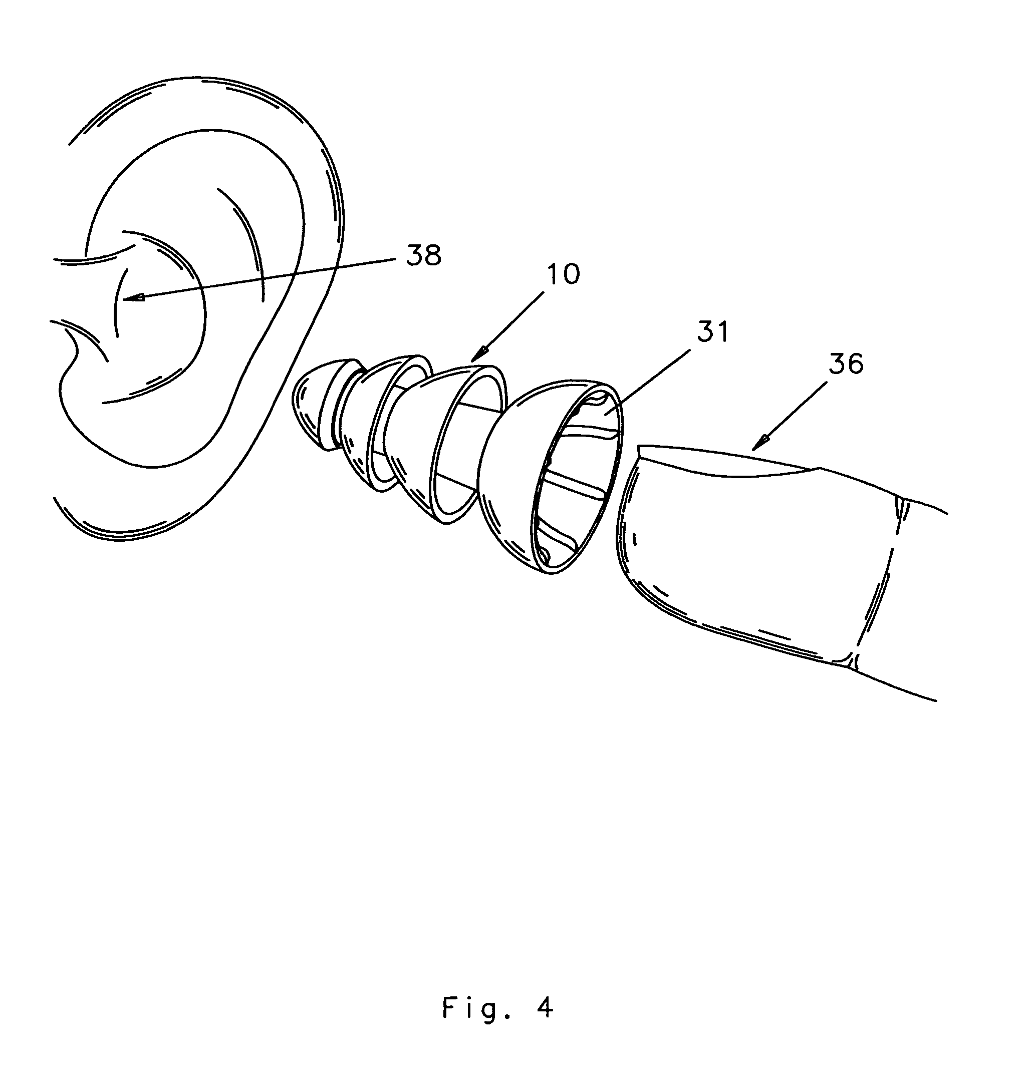
[0017]As can be seen in FIGS. 1 through 4, an earplug 10 of the present invention is formed by injection molding in a single operation to have two portions 12 and 14 and with portion 12 forming a forward portion and portion 14 forming a rearward portion. The forward portion 12 is to be inserted into the ear canal and with the rearward portion 14 formed as a cup shaped flange to receive a finger of the user to facilitate the insertion of the earplug into the ear canal.

[0018]The portion 12 of the earplug 10 is formed of a shaft section 16, a pair of flanges 18 and 20 and a forward curved front end 22 preferably formed as a bulbous end portion. The flanges 18 and 20 as well as the curved front end 22 each have a generally rounded cone configuration and extend rearward to be received within the ear canal and provide sealing to the walls of the ear canal. As can be seen in FIG. 3, the member 12 has a hollow interior channel 24 which extends the length of the member 12 and has an open end...


PUM


Abstract

An earplug composed of an injected molded resilient polymeric material for insertion into an ear canal by a fingertip of a user, including an elongated member having a nose portion formed as a curved front end. An open cup shaped rearward extending flange located at the end of the elongated member opposite to the nose portion and with the open cup shaped rearward extending flange configured to receive the fingertip of the user. The elongated member including at least one flange element located intermediate the nose portion and the open cup shape flange. The nose portion and the flange element having a generally curved shape to extend into and conform to the wall of the ear canal. The earplug composed of a resilient polymer material having a relatively low Shore A Durometer hardness value and the cup shape flange portion with the inserted fingertip of the user forming a handle of greater stiffness to enable the earplug with the relatively low Shore A Durometer hardness value to be more easily inserted into the ear canal.

Description

BACKGROUND OF THE INVENTION[0001]1. Field of the Invention[0002]The present invention relates to an earplug and more specifically is directed to an injection molded resilient thermoplastic elastomer (TPE) earplug having at least one flange and useful as a hearing protector.[0003]2. Description of the Prior Art[0004]There are presently on the market a number of earplugs that include a central shaft and extending there from at a nose end at least a single flange. The earplugs are generally composed of an injection molded resilient thermoplastic elastomer material such as synthetic rubber material. The flange element extends outwardly from the nose end of the shaft member and also extends rearward from the nose end and is so spaced so as to provide a free annular space between the flange and the shaft. One basic earplug of this type is generally referred to as the V-51R earplug and was developed during the course of World War II in order to provide improved hearing protection to member...

Claims


Application Information

Patent Timeline
Patent Type & Authority Patents(United States)
IPC IPC(8): A61F11/00
CPCA61F11/08
Inventor MAGIDSON, MARK
Owner MOLDEXMETRIC
Learn More