Pneumatic tire with tread having circumferential grooves and arcuate grooves

a technology of pneumatic tires and arcuate grooves, which is applied in the field of pneumatic tires, can solve the problems of polygonal wear, uneven shoulder wear of the inner side of the vehicle, etc., and achieve the effect of reducing vehicle exterior noise and improving wet performan

Active Publication Date: 2009-12-15
THE YOKOHAMA RUBBER CO LTD
View PDF28 Cites 4 Cited by
  • Summary
  • Abstract
  • Description
  • Claims
  • Application Information

AI Technical Summary

Benefits of technology

[0005]An object of the present invention is to provide a pneumatic tire which is capable of improving a wet performance and reducing vehicle exterior noise at the same time while ensuring a dry performance.
[0007]According to the present invention, in the pneumatic tire with a designated fitting direction relative to a vehicle, the center land portion is defined as the rib while the multiple arcuate grooves are provided on the second land portions so that an end of each of the arcuate grooves is connected to the main groove on the inner side of the vehicle and the other end of the arcuate groove is connected to the adjacent arcuate groove. Moreover, the proportion Po / Pi between the repeat pitch Po of the arcuate grooves at the second land portion on the outer side of the vehicle and the repeat pitch Pi of the arcuate grooves at the second land portion on the inner side of the vehicle is defined in the above-described range. As a result, it is possible to improve the wet performance and reduce the vehicle exterior noise while ensuring the dry performance.
[0008]In the present invention, it is preferable that a plurality of lug grooves extending in a width direction of the tire are provided on each of a pair of shoulder land portions located respectively in shoulder regions of the tread portion. These lug grooves on the shoulder land portions contribute to improvement in the wet performance. Moreover, when providing the lug grooves on the shoulder land portions, it is preferable that a thin groove extending in the circumferential direction of the tire is provided on the shoulder land portion on the inner side of the vehicle so as to define a rib between the thin groove and the main groove located at the innermost position on the inner side of the vehicle, the rib extending continuously in the circumferential direction of the tire without being sectioned. That is, when the lug grooves are provided on the shoulder land portions, especially the shoulder land portion on the inner side of the vehicle is apt to be worn unevenly (polygonal wear). However, such uneven wear can be suppressed by the rib disposed at a part of the shoulder land portion on the inner side of the vehicle.
[0009]Here, it is preferable to form the lug grooves on the shoulder land portion on the inner side of the vehicle so as to be connected to the thin groove, and to form the lug grooves on the shoulder land portion on the outer side of the vehicle so as to be connected to the main groove located at the outermost position on the outer side of the vehicle. By connecting the lug grooves on the shoulder land portion on the outer side of the vehicle to the main groove located at the outermost position on the outer side of the vehicle as described above, it is possible to improve a drainage performance when the vehicle is turning on a wet road.
[0010]It is preferable to set a proportion of a groove width of the main groove located at the outermost position on the outer side of the vehicle to a groove width of the rest of the main grooves in a range from 0.6 to 0.9. Meanwhile, it is preferable to set a proportion of a groove width (a groove width of the narrowest portion) of the lug grooves at the shoulder land portion on the outer side of the vehicle to a groove width (a groove width of the narrowest portion) of the lug grooves at the shoulder land portion on the inner side of the vehicle in a range from 0.6 to 0.9. That is, by setting relatively small groove widths of the main grooves and the lug grooves, on the outer side of the vehicle, having a large influence on the vehicle exterior noise, it is possible to reduce the vehicle exterior noise.

Problems solved by technology

That is, when the lug grooves are provided on the shoulder land portions, especially the shoulder land portion on the inner side of the vehicle is apt to be worn unevenly (polygonal wear).

Method used


Image

  • Pneumatic tire with tread having circumferential grooves and arcuate grooves
  • Pneumatic tire with tread having circumferential grooves and arcuate grooves

Examples


examples

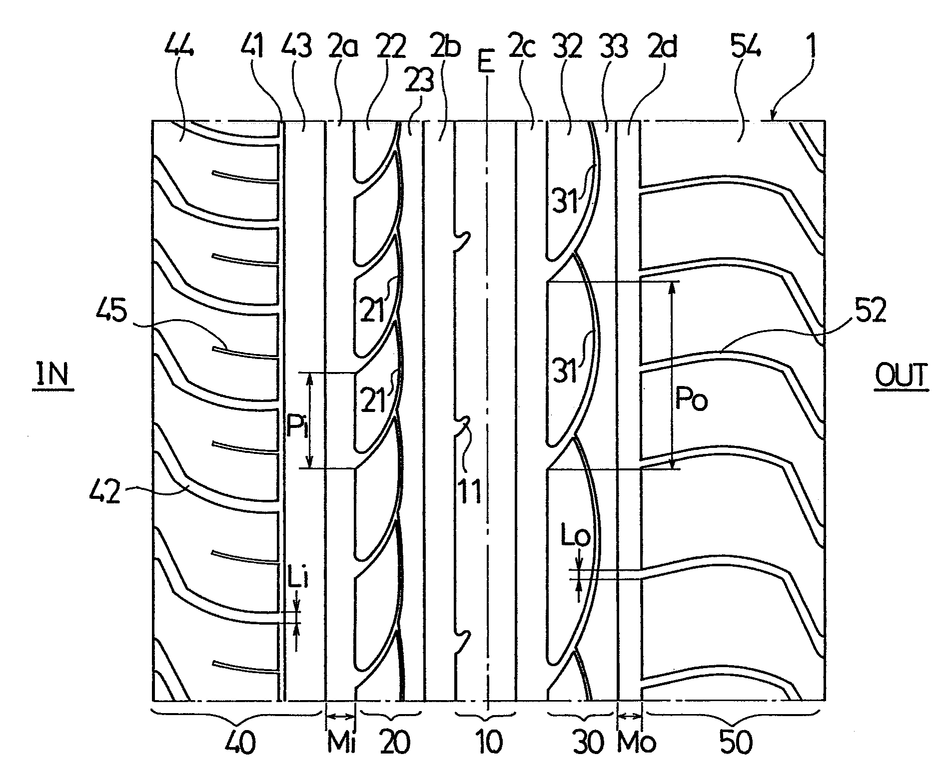
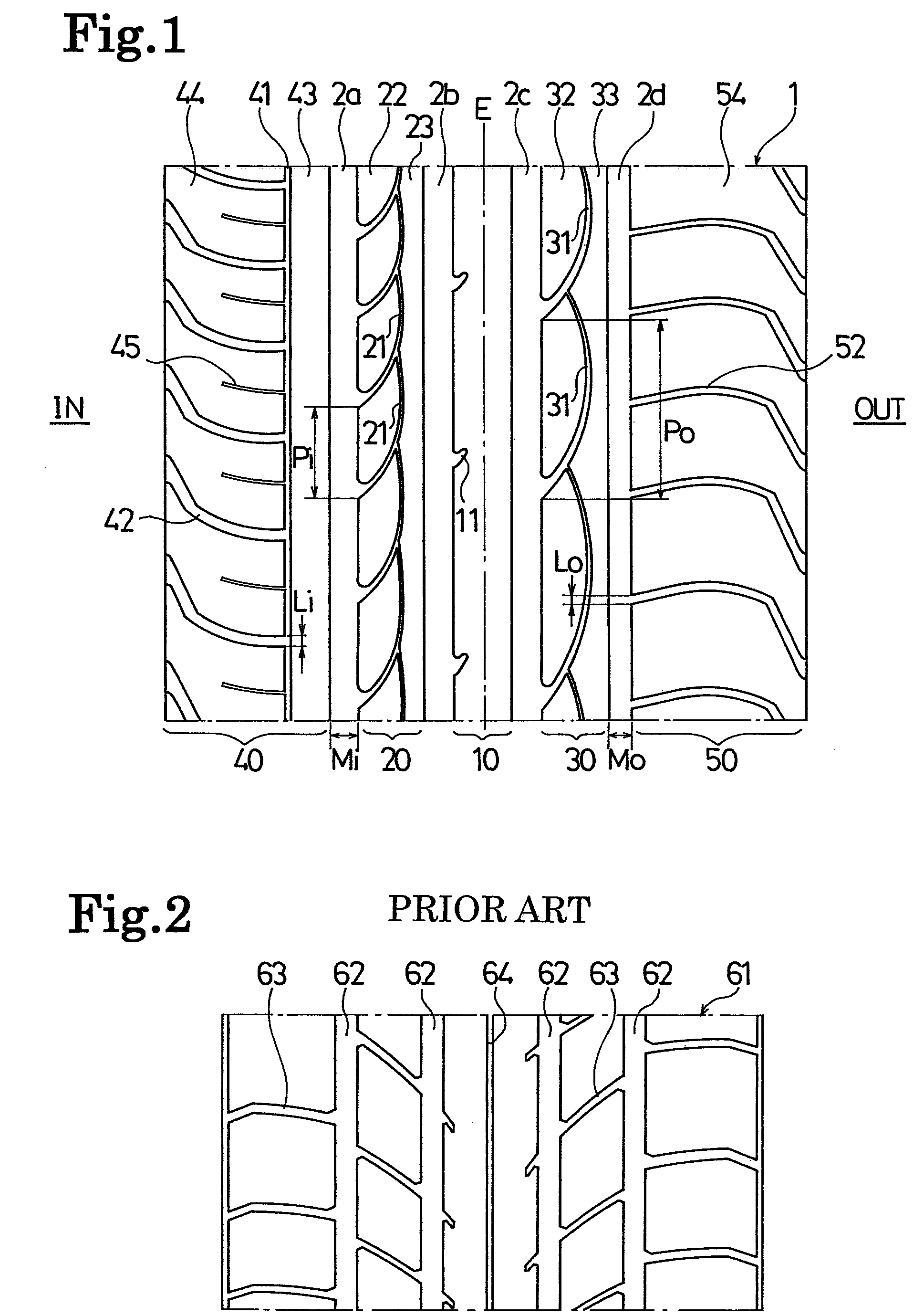
[0031]Pneumatic tires (Examples 1 to 3 and Comparative Example 1) having a tire size of 245 / 40R18 and a tread pattern as shown in FIG. 1 and a pneumatic tire (Conventional Example 1) having the same tire size and a tread pattern as shown in FIG. 2 are manufactured. Here, the tread pattern shown in FIG. 2 represents a directional pattern that provides a tread portion 61 with main grooves 62, lug grooves 63, and a thin groove 64.

[0032]In Examples 1 to 3 and in Comparative Example 1, the proportion Po / Pi between the repeat pitch Po of the arcuate grooves at the second land portion on the outer side of the vehicle and the repeat pitch Pi of the arcuate grooves at the second land portion on the inner side of the vehicle, the proportion Mo / Mi between the groove width Mo of the main groove located at the outermost position on the outer side of the vehicle and the groove width Mi of the other main grooves, and the proportion Lo / Li between the groove width Lo of the lug grooves at the should...


PUM


Abstract

Provided is a pneumatic tire in which improvement is achieved in a wet performance and reduction in vehicle exterior noise while ensuring a dry performance. The pneumatic tire has a designated fitting direction relative to a vehicle, in which four main grooves extending in a circumferential direction of the tire are provided on a tread portion, two grooves out of these main grooves are located on each of both sides of a tire equator, five lines of land portions are defined by the main grooves, a center land portion located on the tire equator is a rib which continuously extends in the circumferential direction of the tire without being sectioned, a plurality of arcuate grooves each extending in an arc shape are provided on each of a pair of second land sections located respectively on both sides of the center land section, an end of each of the arcuate grooves is connected to the main groove on an inner side of the vehicle, another end of the arcuate groove is connected to the adjacent arcuate groove, a repeat pitch Po of the arcuate grooves on the second land portion located on an outer side of the vehicle is set greater than a repeat pitch Pi of the arcuate grooves on the second land portion located on the inner side of the vehicle, and a proportion Po / Pi of the pitches is set in a range from 1.5 to 3.0.

Description

BACKGROUND OF THE INVENTION[0001]The present invention relates to a pneumatic tire with a designated fitting direction relative to a vehicle, or more specifically to a pneumatic tire capable of improving a wet performance and reducing vehicle exterior noise while ensuring a dry performance.[0002]A dry performance of a pneumatic tire is degraded when raising a groove area ratio on a tread portion in order to improve a wet performance of the tire. On the other, vehicle exterior noise tends to be increased when a lug groove component on the tread portion is increased in order to improve the wet performance. Accordingly, it is difficult to satisfy all demands for improvements in the dry performance, the wet performance, and the reduction in vehicle exterior noise at the same time.[0003]Conventionally, in order to achieve a good balance among the dry performance, the wet performance, and the reduction in vehicle exterior noise, there has been proposed a pneumatic tire having a designated...

Claims


Application Information

Patent Timeline
Patent Type & Authority Patents(United States)
IPC IPC(8): B60C11/03
CPCB60C11/0309B60C11/0318B60C11/0304B60C2011/0374Y10S152/903B60C2011/0388
Inventor IKEGAMI, TETSUO
Owner THE YOKOHAMA RUBBER CO LTD
Why Eureka
Try Eureka