High-brightness LED-phosphor coupling

a ledphosphor and coupling technology, applied in the direction of refractors, lighting and heating apparatus, display means, etc., can solve the problems of color shift, unfavorable many applications of large light sources, and decrease of light outpu

Active Publication Date: 2006-09-19
IDEAL IND LIGHTING LLC
View PDF17 Cites 41 Cited by
  • Summary
  • Abstract
  • Description
  • Claims
  • Application Information

AI Technical Summary

Problems solved by technology

This larger light source is unfavorable for many applications, especially those requiring that the light be collected and redirected into a highly collimated beam of light within a limited output aperture, for example flashlights, spotlights, and automotive headlight high beams.
The resulting high temperature causes color shifts due to the temperature sensitivity of the phosphor light emission.
High temperatures also subject both binder and phosphor to temperature related degradation, which decreases light output over time.
White LEDs accoding to FIG. 2 are also subject to color non-uniformity, as light emitted directly by the LED has a different spatial or angular pattern from light emitted by the phosphor.

Method used


Image

  • High-brightness LED-phosphor coupling
  • High-brightness LED-phosphor coupling
  • High-brightness LED-phosphor coupling

Examples


Embodiment Construction

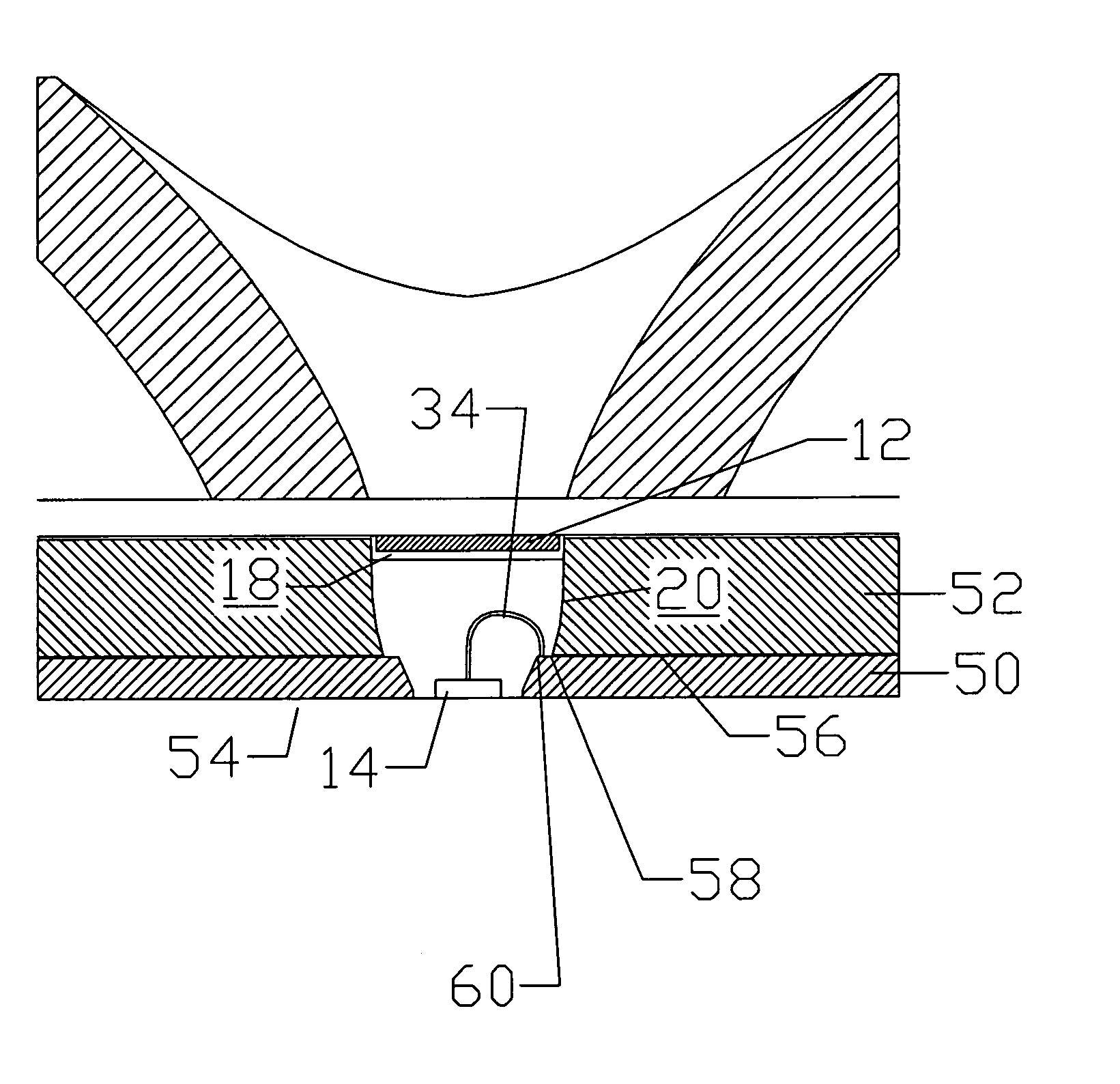
[0011]FIG. 3 shows one embodiment of the current invention, shown generally at 10. The phosphor is deposited in a layer 12 separated from the die 14 by a significant thickness of clear encapsulant 16. The phosphor 12 is immersed in a medium 18 having an optical index n2 lower than that of the encapsulant 16. In one embodiment of FIG. 3 the medium 18 is air. The phosphor 12 spatial area is larger than the die 14, but by virtue of this lower index the phosphor layer 12 has an optical etendue comparable to that of the die 14 itself. A non-imaging optical coupler 20 collects the majority of the light from the die 14 and redirects it to the phosphor 12 while maintaining the etendue comparable to the die 14.

[0012]The non-imaging optical coupler 20 can have a variety of forms as described in many known publications and U.S. patents. The shape of the coupler 20 should redirect most of the light from the die 14 from very large angles inside the encapsulant 16 to angles smaller than the criti...


PUM


Abstract

A high brightness LED phosphor coupling device. A semiconductor light source is encapsulated by a medium of first index of refraction, a layer of phosphor surrounded by a second medium of second index of refraction of optical index less than the first index and a light coupler for redirecting most of the light from the light source to an area of the phosphor about equal to the area of the light source multiplied by the square of the ratio of the first to the second index of refraction.

Description

[0001]This application claims priority to U.S. Provisional Patent Application No. 60 / 469,649, filed on May 12, 2003, and incorporated herein by reference.[0002]This invention is directed to a high brightness LED-phosphor coupling device. More particularly the invention is directed to a semiconductor light source encapsulated by a medium of first index of refraction, a layer of phosphor surrounded by a second medium of second optical index less than the first index and a light coupler for redirecting most of the light from the light source to an area of the phosphor about equal to the area of the light source multiplied by the square of the ratio of the first to the second index of refraction.BACKGROUND AND PRIOR ART[0003]Light-emitting diodes (LEDs) are a commonly used light source in applications including lighting, signaling, signage, and displays. LEDs have several advantages over incandescent and fluorescent lamps, including high reliability, long lifetime, and high efficiency. ...

Claims


Application Information

Patent Timeline
Patent Type & Authority Patents(United States)
IPC IPC(8): F21V9/16H01L25/075H01L33/50H01L33/56H01L33/60
CPCH01L33/507H01L25/0753H01L33/56H01L33/60Y10S362/80H01L2224/48091H01L2224/73265H01L2924/00014H01L2924/00
Inventor JACOBSON, BENJAMIN A.GENGELBACH, ROBERT D.
Owner IDEAL IND LIGHTING LLC
Why Eureka
Try Eureka