Cord reel box with recharging unit

a rechargeable unit and reel box technology, applied in the direction of machines/engines, mechanical equipment, arrangements using take-up reels/drums, etc., can solve the problems of not being able to recharge and provide electrical power

Inactive Publication Date: 2006-09-19
LIAO SHENG HSIN
View PDF9 Cites 25 Cited by
  • Summary
  • Abstract
  • Description
  • Claims
  • Application Information

AI Technical Summary

Problems solved by technology

However, the cord reeling device only can retract cord, but cannot recharge and provide electrical power.

Method used


Image

  • Cord reel box with recharging unit
  • Cord reel box with recharging unit
  • Cord reel box with recharging unit

Examples


Embodiment Construction

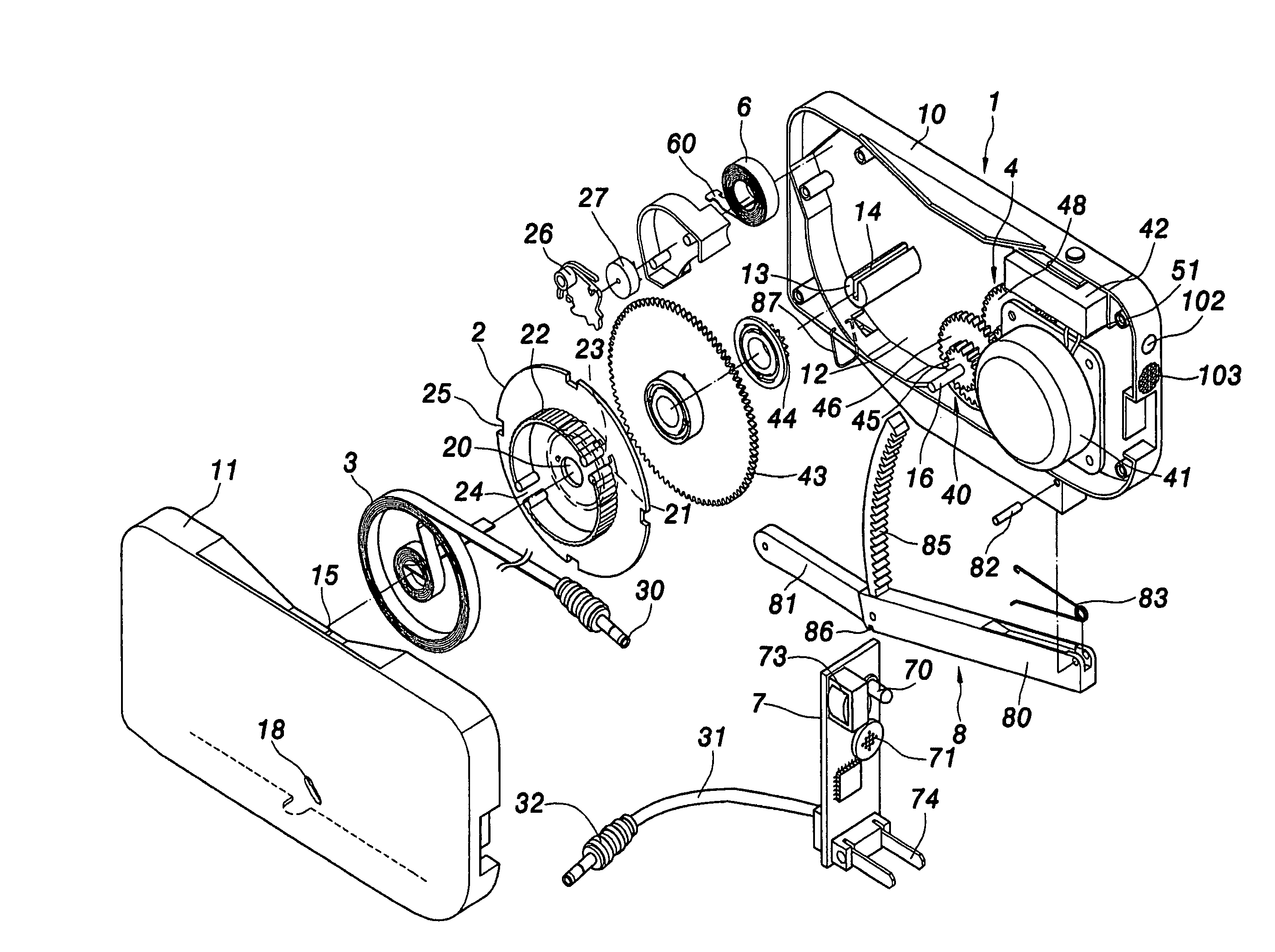
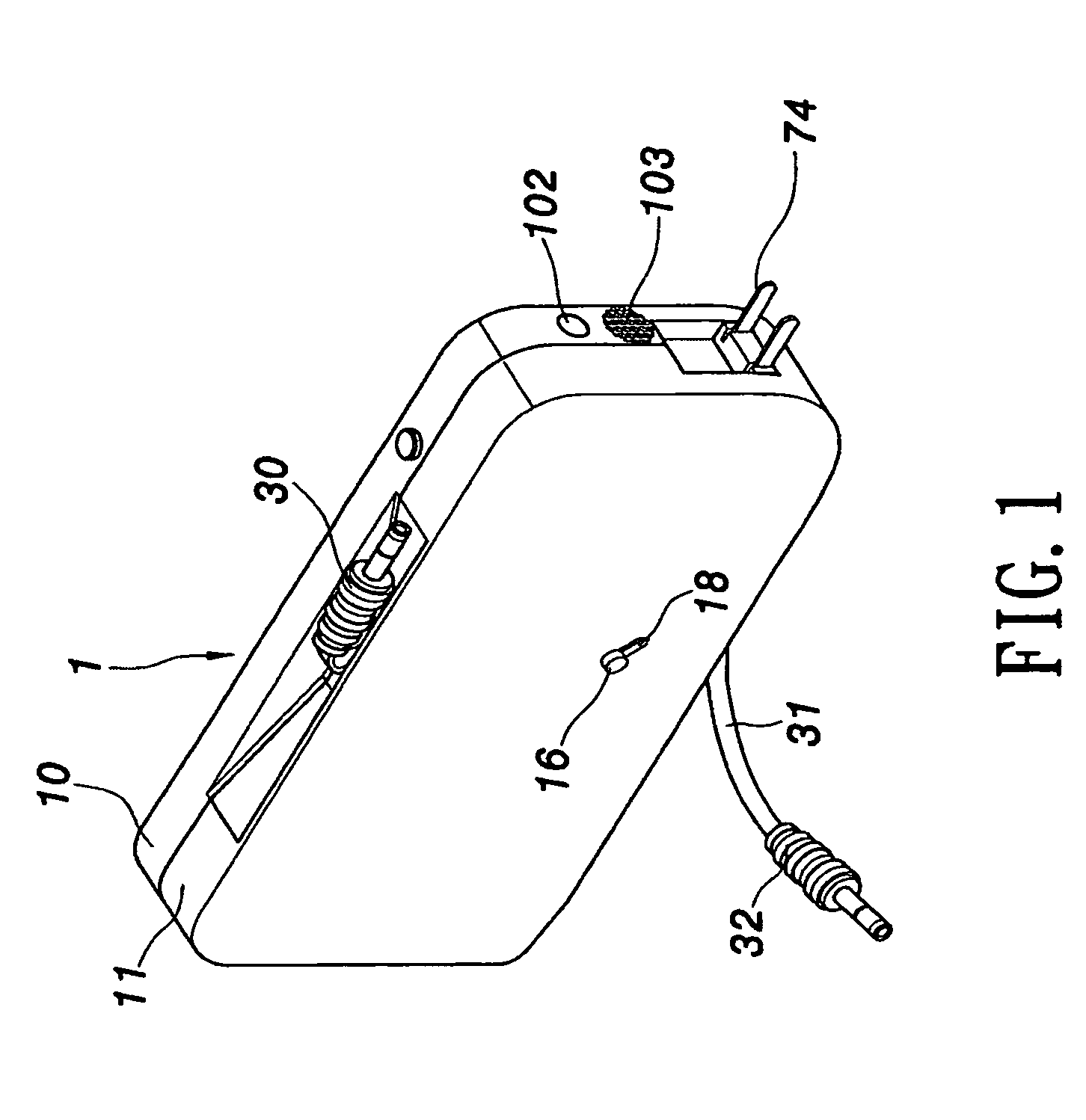
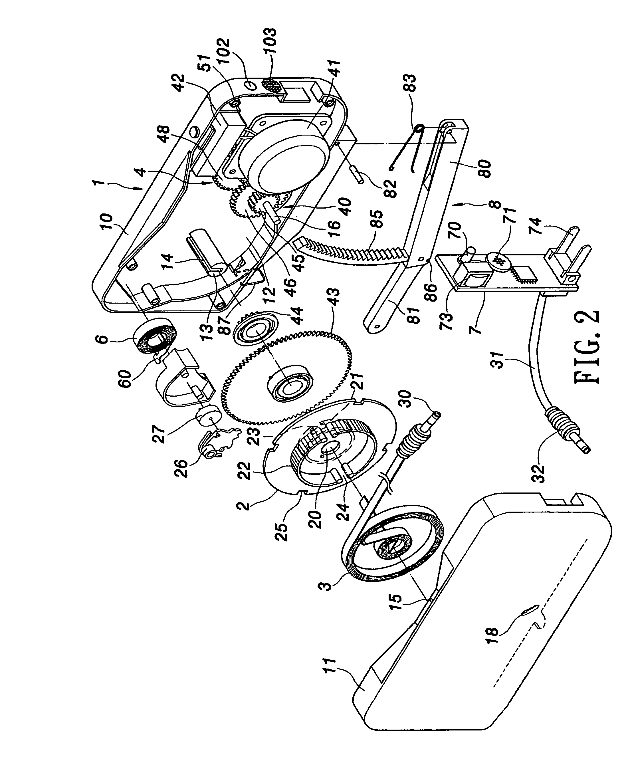
[0021]Turning now to the drawings, FIGS. 1 to 5 show a cord reel box with recharging unit. The cord reel box with recharging unit comprises a housing 1, a rotating plate 2, a communication cord 3, a recharging unit 4, a PCB 7, and a pressing device 8. The housing 1 has a first half-housing 10, and a second half-housing 11 connecting with the first half-housing 10 to form with a cavity 12 therein. A pivoting shaft 13 is disposed in the cavity 12 of the housing 1. A cord slot 14 is formed in the pivoting shaft 13, and a cord outlet 15 is formed on one side of the housing 1. The PCB 7 is mounted in the housing 1 and adjacent to the recharging unit 4.

[0022]The rotating plate 2 has a pivoting hole 20 for being pivotally mounted on the pivoting shaft 13, a first and a second rings 21, 22 respectively formed on two sides of the rotating plate 2. A volute spring 6 is arranged between the housing 1 and the rotating plate 2 for urging the rotation of the rotating plate 2. The volute spring 6 ...


PUM


Abstract

A cord reel box with recharging unit has a housing, a rotating plate, a volute spring, a communication cord, a recharging unit, and a pressing device. The gear mechanism is assembled between the rotating plate and the regenerator. The pressing device is pivotally mounted on one side of the housing. The gear mechanism is assembled between the pressing device and the regenerator. An AC plug is mounted on the housing and electrically connecting with the PCB. The PCB has a transformer mounted thereon, and the communication cord electrically connects with the PCB. The cord reel box can recharge a cell phone via the recharging unit or plug with the AC plug.

Description

BACKGROUND OF THE INVENTION[0001]1. Field of the Invention[0002]The present invention relates to a cord reel box with recharging unit, and particularly to a cord reel box combined with a recharging unit not only for extending and rewinding a communication cord, but also for generating or recharging electric power while pulling the communication cord or by pressing a handle.[0003]2. Description of the Prior Art[0004]Use of any communication device, such as a computer, modem, telephone, or a fax machine, requires connection of a proper communication cord for transmission of electrical messages. Several types of cord reeling devices exist to allow such a communication cord to be sufficiently long for practical use while avoiding entanglement of the same. The cord reeling device basically comprises a housing, a communication cord, a rotating plate and a volute spring. A connector of the communication cord can thus connect with an associated communication device for providing transmissio...

Claims


Application Information

Patent Timeline
Patent Type & Authority Patents(United States)
IPC IPC(8): H02K7/116B65H75/48
CPCB65H75/4434H02K7/1853H02G11/02B65H2701/34
Inventor LIAO, SHENG HSIN
Owner LIAO SHENG HSIN
Why Eureka
Try Eureka