
Method and apparatus for determining the straightness of tubes and bars

a technology of straightness and tube, applied in the direction of measuring devices, manufacturing tools, instruments, etc., can solve the problems of not being able to detect deviation trends, consuming a considerable amount of time for typical inspection procedures, and a large amount of produced materials without quantitative inspections

Inactive Publication Date: 2006-09-19
TIMKENSTEEL CORP
View PDF2 Cites 63 Cited by
  • Summary
  • Abstract
  • Description
  • Claims
  • Application Information

AI Technical Summary

Problems solved by technology

But this leaves much of the produced material without a quantitative inspection, and fails to detect deviation trends that could be corrected by making adjustment in the operation of the mill.
If quantitative inspection results are required, the typical inspecting procedure consumes a considerable amount of time, and without incurring inordinate expense, cannot be performed on all points of the material from a full production run at a mill.

Method used


Image

  • Method and apparatus for determining the straightness of tubes and bars
  • Method and apparatus for determining the straightness of tubes and bars
  • Method and apparatus for determining the straightness of tubes and bars

Examples


Embodiment Construction

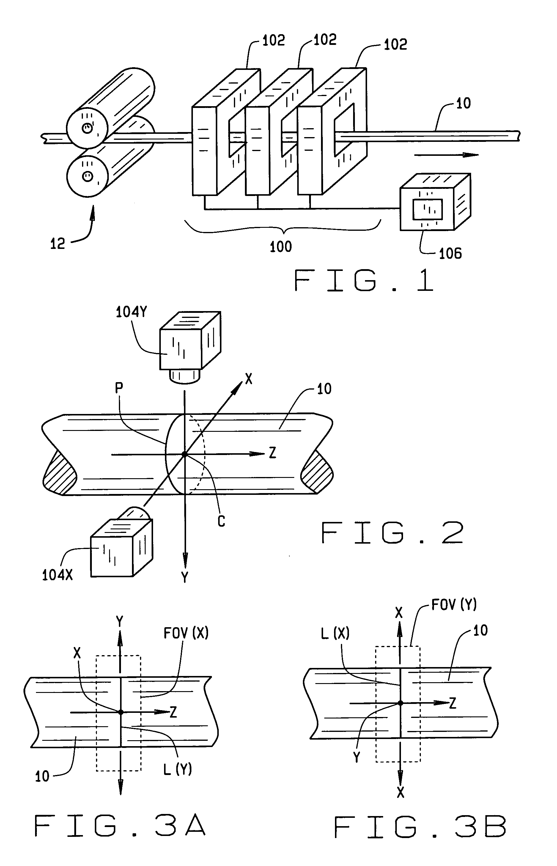
[0021]Turning to FIG. 1, a length of linear stock material 10 exiting a mill production line 12 is passed through a non-contact straightness measurement system of the present invention, shown generally at 100. In one embodiment, the measurement system 100 comprises at least three imaging modules, shown generally at 102, which are disposed in a linearly spaced configuration along a common longitudinal axis corresponding to the direction of travel for the linear stock material 10. Preferably, each imaging module 102 is spaced apart by approximately ½ the straightness reference length.

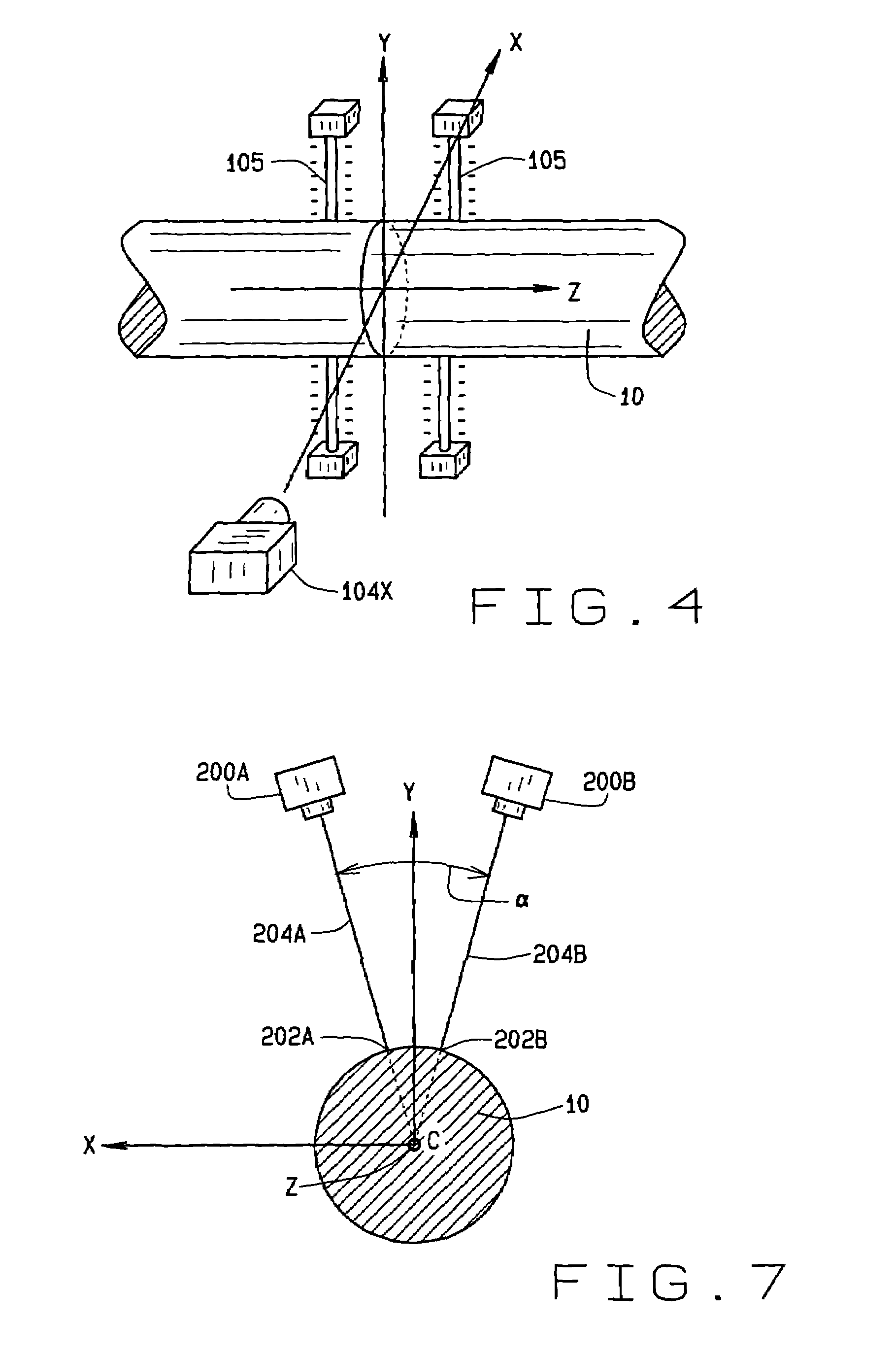
[0022]Each imaging module 102 includes a pair of orthogonally disposed imaging sensors 104X and 104Y, each having a field of view aligned with a cross-sectional plane P of the linear stock material 10 passing through the imaging module 102, as best seen in FIG. 2. The specific angular orientation of the pair of imaging sensors 104X and 104Y about the longitudinal axis of the linear stock material 10 is no...


PUM

PropertyMeasurementUnit
Lengthaaaaaaaaaa
Distanceaaaaaaaaaa
Separationaaaaaaaaaa

Abstract

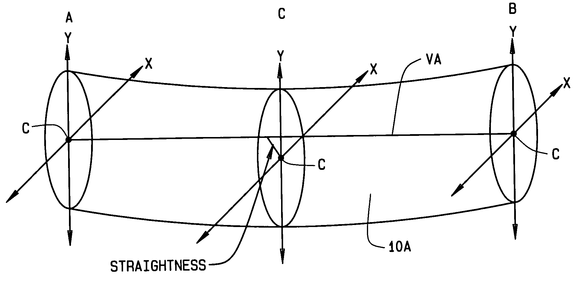
A method and apparatus for automating the measurement of straightness of linear stock material produced by the operation of a mill. As the linear stock material exits from the mill, sensors acquire a sequence of image or distance measurement pairs associated with the material at discrete longitudinal points over a segment of the material. A processing system utilizes the data pairs to determine a set of centroids for a segment of the material. A virtual axis is identified between centroids associated with the segment, and the processing system determines a measure of deviation of each remaining centroid in a segment from the virtual axis to identify a degree of concavity of the material within the segment, as well as to identify a measure of the angular orientation of the concavity about the virtual axis.

Description

CROSS-REFERENCE TO RELATED APPLICATIONS[0001]Not Applicable.STATEMENT REGARDING FEDERALLY SPONSORED RESEARCH[0002]Not Applicable.BACKGROUND OF THE INVENTION[0003]This invention relates in general to the production of linear stock material such as tube stock material and round bar stock material, and more particularly to an machine vision method and apparatus for the automated determination of the straightness of linear stock material during production.[0004]Ideally, tube stock and round bar stock materials, generally referred to herein as linear stock material, should emerge from the mills in which they are produced in a perfectly straight configuration for the entire production length. But typically some deviation from perfectly straight exists in the linear stock material, which is acceptable for most purposes so long as the deviation is within prescribed tolerances. Currently mill operators conduct visual inspections to determine if sections of the linear stock material being pro...

Claims


Application Information

Patent Timeline
IPC IPC(8): G01B7/00G01B15/00
CPCG01B11/245G01B11/2433B21B38/00
Inventor DEFFENBAUGH, MARKSEIFERT, MICHAEL
Owner TIMKENSTEEL CORP
Learn More