Buckle

a buckle and buckle technology, applied in the field of buckles, can solve the problems of inability to obtain a small-sized buckle having a good appearance, affecting the appearance of the buckle, etc., and achieves the effects of easy elastic deformation, good appearance, and small siz

a buckle and buckle technology, applied in the field of buckles, can solve the problems of inability to obtain a small-sized buckle having a good appearance, affecting the appearance of the buckle, etc., and achieves the effects of easy elastic deformation, good appearance, and small siz

US7111368B2Inactive Publication Date: 2006-09-26YKK CORP

Image

  • Buckle
  • Buckle
  • Buckle

Examples


Embodiment Construction

[0044]An embodiment of a buckle according to the invention will be specifically described below with reference to the drawings.

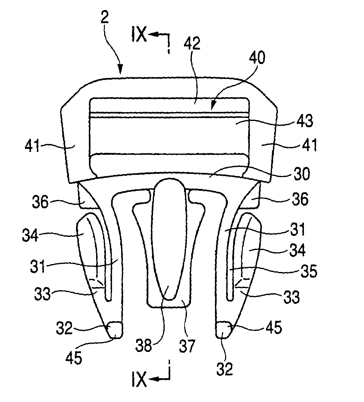
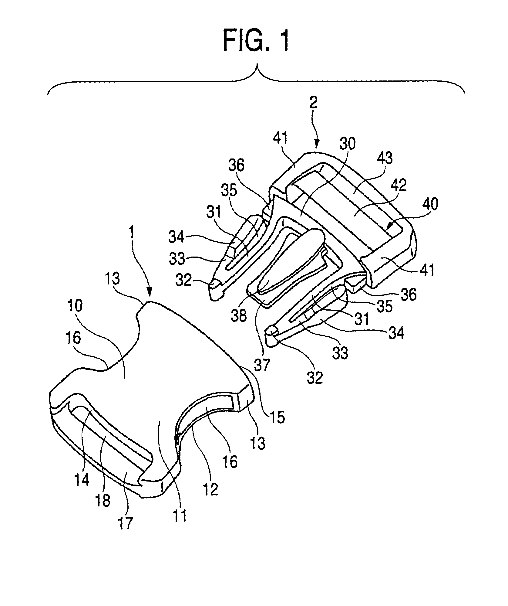
[0045]The buckle according to the invention is, as shown in FIG. 1, of an insertion type having a buckle body 1 called socket and an insertion member 2 called plug which can be inserted into the buckle body 1. Both the buckle body 1 and the insertion member 2 are formed by injection molding means using a thermoplastic resin, for example, polyamide, polyacetal, polypropylene or polybutylene terephthalate.

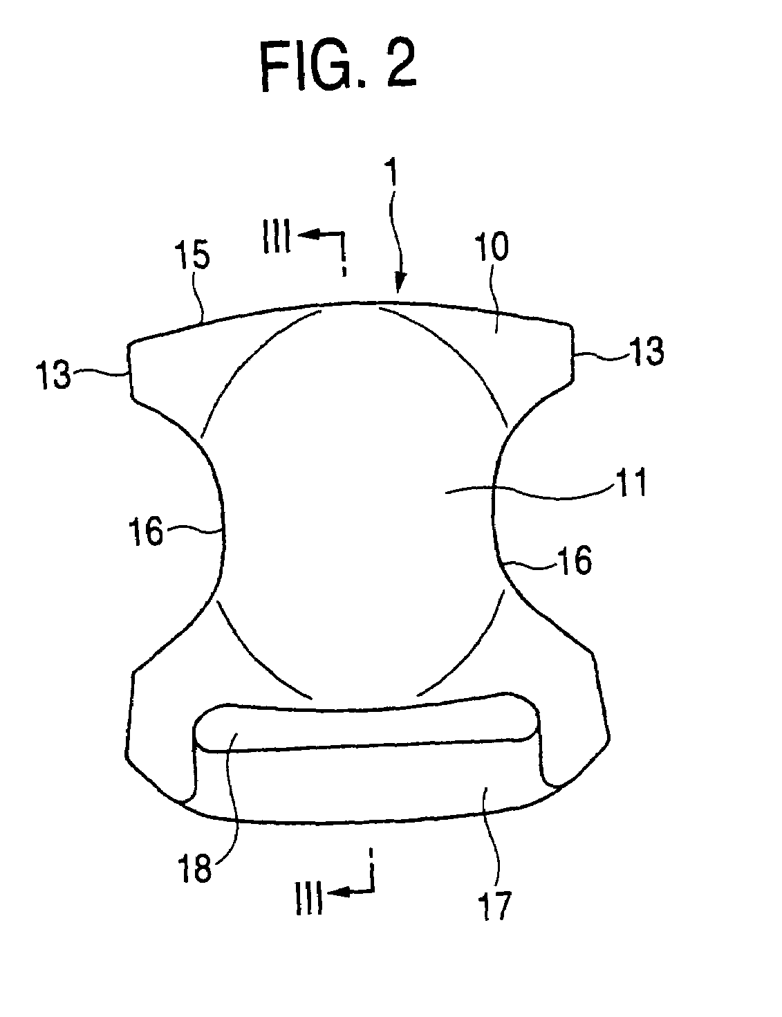
[0046]As shown in FIGS. 1 to 5, the buckle body 1 forms a housing 10 to enclose an upper plate 11, a lower plate 12, left and right side walls 13 and 13, and a front wall 14. One of the ends of the housing 10 is provided with an insertion port 15 into which the insertion member 2 can be inserted. A circular arc-shaped opening portion 16 is provided on both sides of the housing 10 by partially cutting away the side wall 13, the upper plate 11 and the lower pla...


PUM


Abstract

A buckle body formed of a resin has a housing having an insertion port on one end, an opening portion on both sides and an engaged portion in an inner part, an insertion member is provided with a pair of flexible insertion leg portions including an engaging portion on one end, an operating rod extended like a cantilever from a tip is continuously provided on the outside of the insertion leg portion and a mechanism capable of suppressing inward and outward deformations of the leg portion within a constant rage is provided, and the operating rod is provided with an operating portion protruded outward from the opening portion disposed on the buckle body at time of an insertion into the buckle body, and the insertion leg portion is deformed by pressing to disengage the engaging portion from the engaged portion, thereby removing the insertion member from the buckle body.

Description

BACKGROUND OF THE INVENTION[0001]1. Field of the Invention[0002]The present invention relates to a buckle of an insertion type having a housing-shaped buckle body and an insertion member including a leg portion formed by a projection piece for an insertion, and particularly to a buckle for a belt which is generally used in clothes, bags, helmets or sporting goods.[0003]2. Description of the Related Art[0004]As shown in FIG. 15, there has conventionally been known a buckle of an insertion type having a housing-shaped buckle body 101 and an insertion member 151 including an insertion leg portion 153. The insertion member 151 is provided with an insertion leg portion 153 on one of the ends of a board 155, in which a projection-shaped engaging portion 157 is provided on both sides of the tip of the insertion leg portion 153, and furthermore, an operating portion 159 overhung toward the side is provided on outside surfaces at both sides of the leg portion. The buckle body 101 is formed b...

Claims


Application Information

Patent Timeline
26 Sep 2006
Publication
US7111368B2
IPC
A44B11/25; A44B11/26
CPC
A44B11/266; Y10T24/45524; Y10T24/45581; Y10T24/45529; A44B11/25
Inventors
MATOBA, HIROSHI