Utility cart

a cart and trolley technology, applied in the field of trolleys, can solve the problems of not including suitable management features for electrical extension cords, carts typically do not include electrical terminals and electrical outlets, and unauthorized removal of devices from trolleys, so as to facilitate easy rolling movement of trolleys and facilitate storage of items used.

Inactive Publication Date: 2006-09-26
KIMBALL INTERNATIONAL
View PDF17 Cites 48 Cited by
  • Summary
  • Abstract
  • Description
  • Claims
  • Application Information

AI Technical Summary

Benefits of technology

[0009]The cover member is slidably mounted to the housing, such as with a pair of standard drawer slide assemblies. The cover member is shaped similar to a drawer, and includes a top tray, a pair of side walls, and a drawer front including a drawer pull. The top tray of the cover member provides a work surface in both the first and second positions of the cover member, and is recessed to prevent items such as papers, transparencies, pens, pencils, etc., from falling off of the top tray. Additionally, the cabinet of the cart includes a pair of doors and a plurality of shelves therein, allowing for easy storage of items used with the projector or other peripheral device. An upper end of the cart additionally includes a handle which may be grasped by a user to facilitate easy rolling movement of the cart from one location to another.

Problems solved by technology

Although such carts are simple in design and are inexpensive, there are a number of disadvantages associated with such carts.
First, the open shelf design of the carts allows access to any peripheral devices which are supported by the carts, potentially allowing unauthorized removal of the devices from the carts.
Further, such carts typically do not include electrical terminals and electrical outlets for easy electrical connection of electronic peripheral devices to a power source, and also do not include suitable electrical extension cord management features.
Rather, such carts typically only provide brackets or other structure upon which an electrical extension cord may be wound.

Method used


Image

  • Utility cart
  • Utility cart
  • Utility cart

Examples


Embodiment Construction

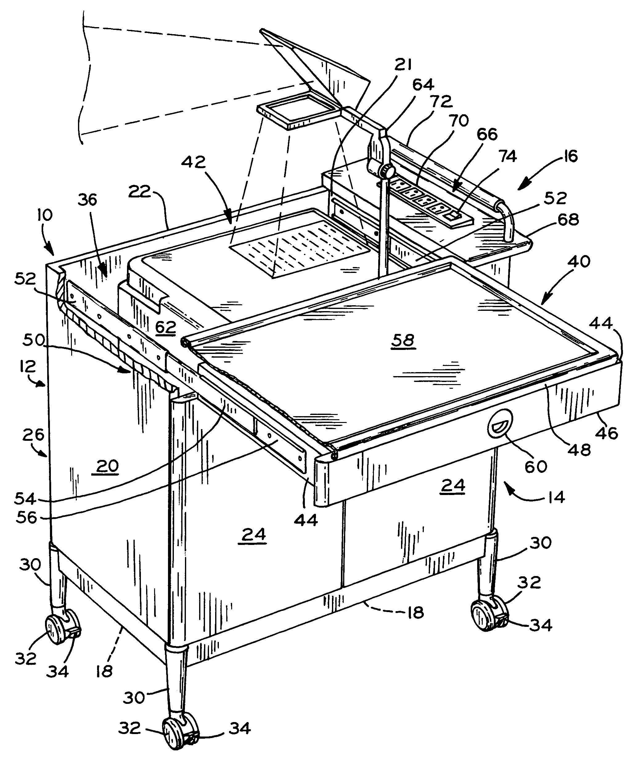
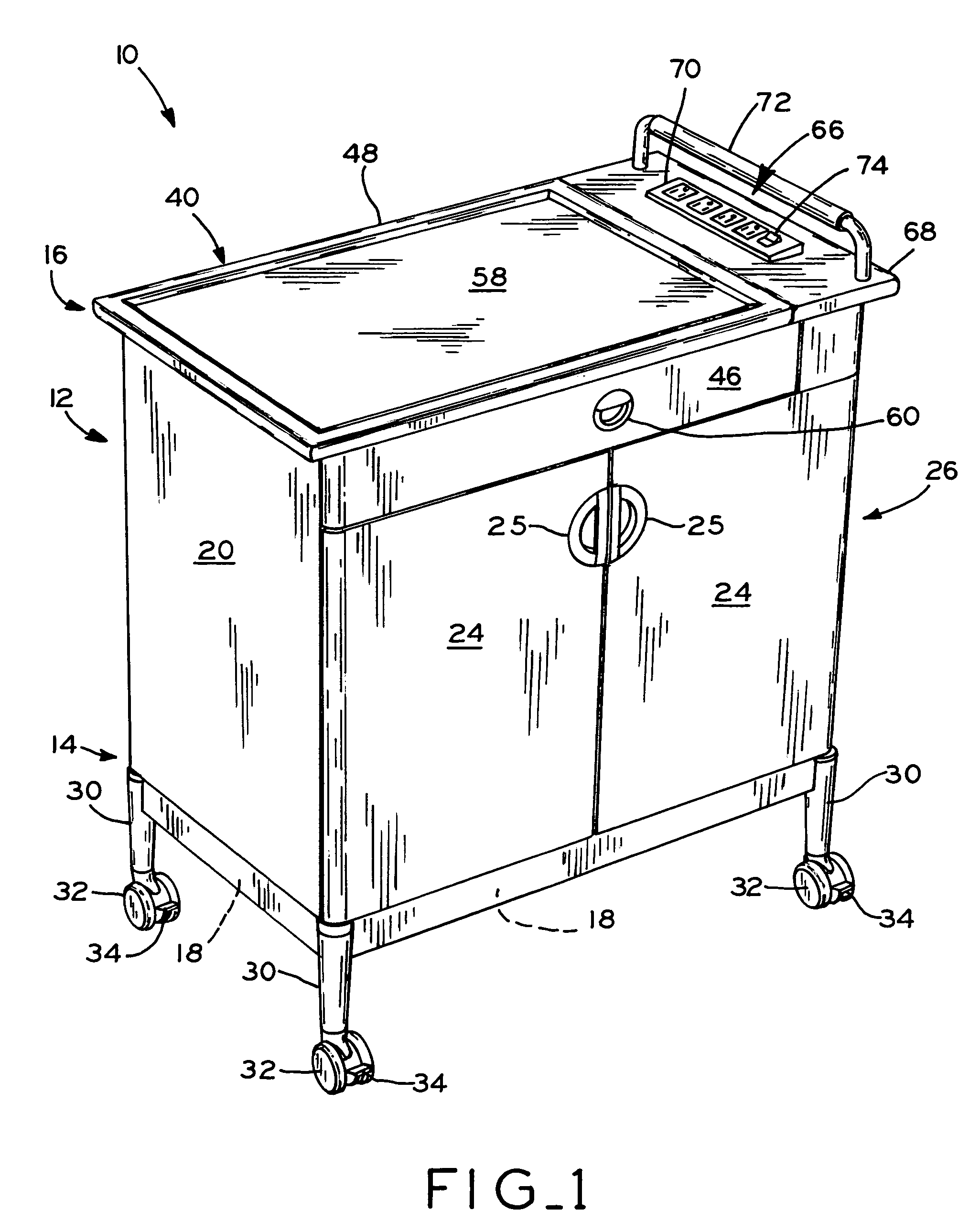
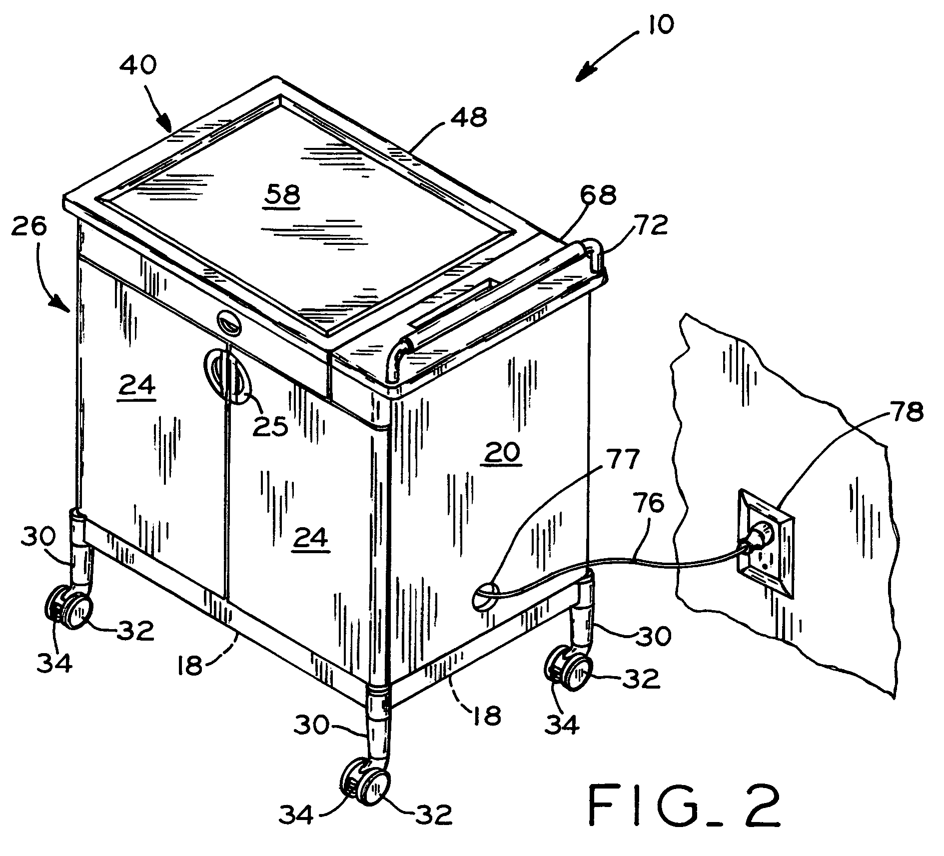
[0022]Referring to FIGS. 1–6, a utility cart 10 according to the present invention is shown, which generally includes housing 12 having lower portion 14 and upper portion 16. Housing 12 generally includes bottom wall 18, a pair of side walls 20, rear wall 22, and a pair of doors 24 hingedly attached to side walls 20. Doors 24 include door pulls 25 for grasping by a user to open doors 24, and doors 24 may further optionally include locks for locking doors 24 in a closed position. Side walls 20, rear wall 22, and doors 24 generally define a cabinet 26 which may include one or more horizontal shelves 28 (FIG. 5) therein. A plurality of legs 30 are attached to bottom wall 18, and each terminate in caster wheels 32 for allowing rolling movement of cart 10 from one location to another along a floor surface. Optionally, casters 32 may include foot-actuated brake assemblies 34 which may be engaged to prevent movement of casters 32 and thereby fix the position of cart 10.

[0023]Referring to F...


PUM


Abstract

A utility cart including a housing portion having a cabinet and a storage compartment disposed above the cabinet. A cover member is slidably mounted to the housing for movement between a first or closed position, in which the cover member is disposed above the storage compartment and substantially encloses the storage compartment, and a second or open position, in which the cover member is disposed in a cantilevered orientation with respect to the housing, such that the storage compartment is substantially exposed. A peripheral device, such as a projector, for example, may be stored within the storage compartment, such that the peripheral device is enclosed within the cart when the cover member is in its first position and is accessible when the cover member is in its second position. Additionally, the housing of the cart may include an electrical terminal incorporated therein for providing electrical power to the peripheral device.

Description

BACKGROUND OF THE INVENTION[0001]1. Field of the Invention[0002]The present invention relates to utility carts of the type commonly used in office or other workspace environments, such as mobile utility carts for storing and transporting various items, or for supporting electronic peripheral units such as television sets, projectors, computers, printers, and the like.[0003]2. Description of the Related Art[0004]One known utility cart includes a metal frame having a plurality of open shelves, and includes casters mounted to the lower portion of the frame to facilitate rolling movement of the cart along a floor surface. The shelves may be used to support electronic peripheral devices such as television sets, projectors, and computers, for example, as well as to store and transport other related items.[0005]Although such carts are simple in design and are inexpensive, there are a number of disadvantages associated with such carts. First, the open shelf design of the carts allows access...

Claims


Application Information

Patent Timeline
Patent Type & Authority Patents(United States)
IPC IPC(8): B62B3/10B62B3/00
CPCB62B3/00
Inventor WOODS, DONALDFLORES, RUBEN
Owner KIMBALL INTERNATIONAL
Why Eureka
Try Eureka