Catadioptric projection objective with adaptive mirror and projection exposure method

a catadioptric and mirror technology, applied in the direction of optical radiation measurement, instruments, photomechanical equipment, etc., can solve the problem of severe asymmetry in the effect, and achieve the effect of improving the imaging quality

Inactive Publication Date: 2006-09-26
CARL ZEISS SMT GMBH
View PDF21 Cites 25 Cited by
  • Summary
  • Abstract
  • Description
  • Claims
  • Application Information

AI Technical Summary

Benefits of technology

The technical effect of this patent is that it describes how different parts can be moved to make sure images are clear and accurate when taking pictures or videos.

Problems solved by technology

This patent discusses various methods used for improving image quality during microlithography processes. It mentions several types of projections objectives such as pure refractive ones, reflective ones with variable positions, and others. Additionally, it highlights techniques related to astigmatism corrections, rotational error compensation, and other issues associated with imaging devices. Overall, the technical problem addressed in this patent is how to improve the accuracy and precision of projecting patterns onto semiconductor wafers during manufacturing procedures.

Method used


Image

  • Catadioptric projection objective with adaptive mirror and projection exposure method
  • Catadioptric projection objective with adaptive mirror and projection exposure method
  • Catadioptric projection objective with adaptive mirror and projection exposure method

Examples


Embodiment Construction

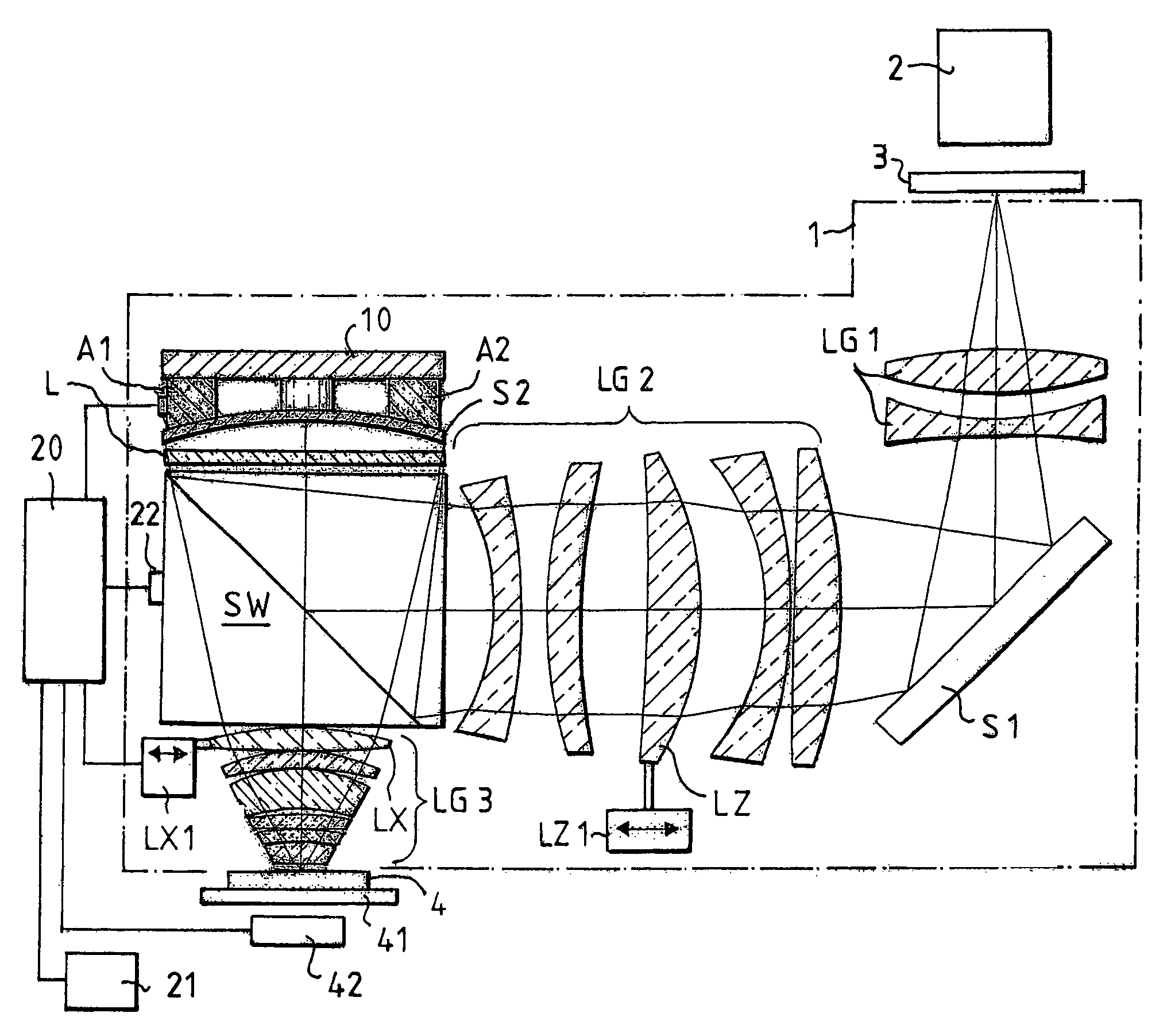
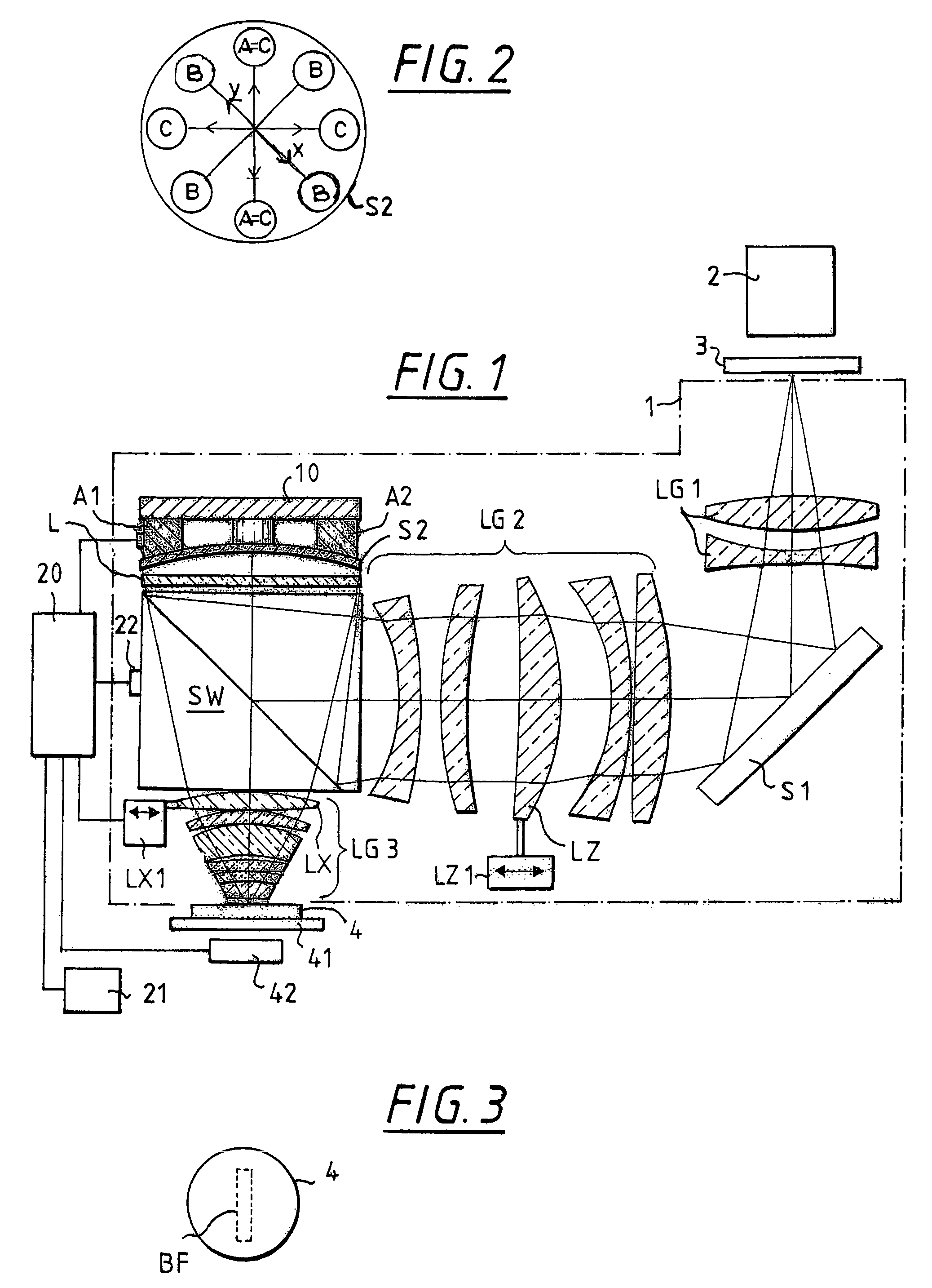
[0025]The core component of the catadioptric projection exposure device according to FIG. 1 is the catadioptric reduction objective 1, in the example shown the embodiment according to FIG. 1 and Table 1 of German Patent Application DE 196 16 922.4 (U.S. patent application Ser. No. 08 / 845,384), which is incorporated herein by reference.

[0026]This catadioptric reduction objective 1 includes a first lens group LG1, a plane deflecting mirror S1, a second lens group LG2, a beam splitter cube SW, a quarter wave plate L, a curved mirror S2 and a third lens group LG3. An illuminating device 2, a mask 3 and a wafer 4 in a holder 41 (wafer chuck) complete the projection exposure device, which is to this extent conventional.

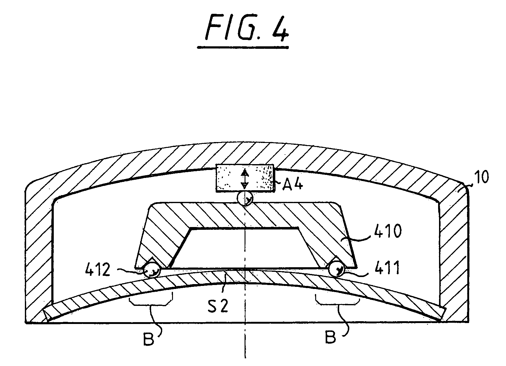
[0027]The curved mirror S2 is newly embodied as an adaptive mirror. Actuators A1, A2 and a frame 10 are provided for this purpose. A sensor 42, e.g., a wavefront sensor, is provided in the region of the wafer 4, and measures a parameter for the imaging quality during exposu...


PUM


Abstract

A catadioptric projection objective for microlithography has at least one curved mirror that is deformable and adjusting elements that can deform the deformable mirror. The adjusting elements are matched to given image errors and their correction. The invention is suitable for astigmatism, fourfold wavefront-deformations due to lens heating, compaction, and the like.

Description


Claims


Application Information

Patent Timeline
Owner CARL ZEISS SMT GMBH
Why Eureka
Try Eureka