Knee protector

a knee protector and knee cap technology, applied in the field of knee protectors, can solve the problems of not providing adequate protection for the knee or the knee cap, affecting the comfort of wearers,

Active Publication Date: 2006-10-03
HILLERICH & BRADSBY
View PDF20 Cites 54 Cited by
  • Summary
  • Abstract
  • Description
  • Claims
  • Application Information

AI Technical Summary

Benefits of technology

[0003]It is an object of the present invention to provide a protecti...

Problems solved by technology

There have been a number of devices proposed for the protection of the knee or the knee cap, but many of these devices either do not provide adequate protection for the knee or knee cap when it comes into contact with the ground or the floor or is extremely cumbersome to the wearer in moving from an upright or standing or moving condition to a bending condition, such as that of a catcher in bas...

Method used


Image

  • Knee protector
  • Knee protector
  • Knee protector

Examples


Embodiment Construction

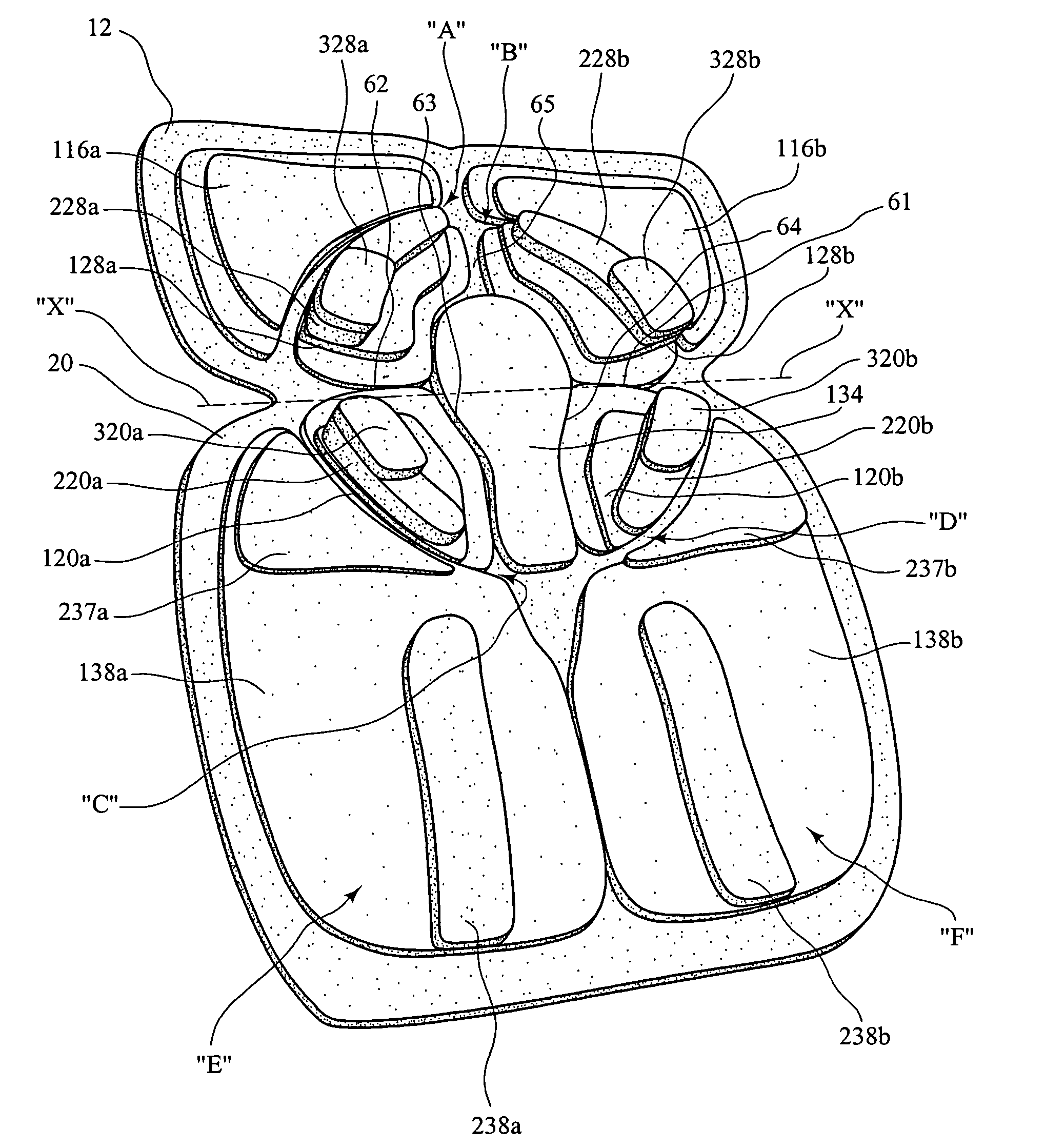
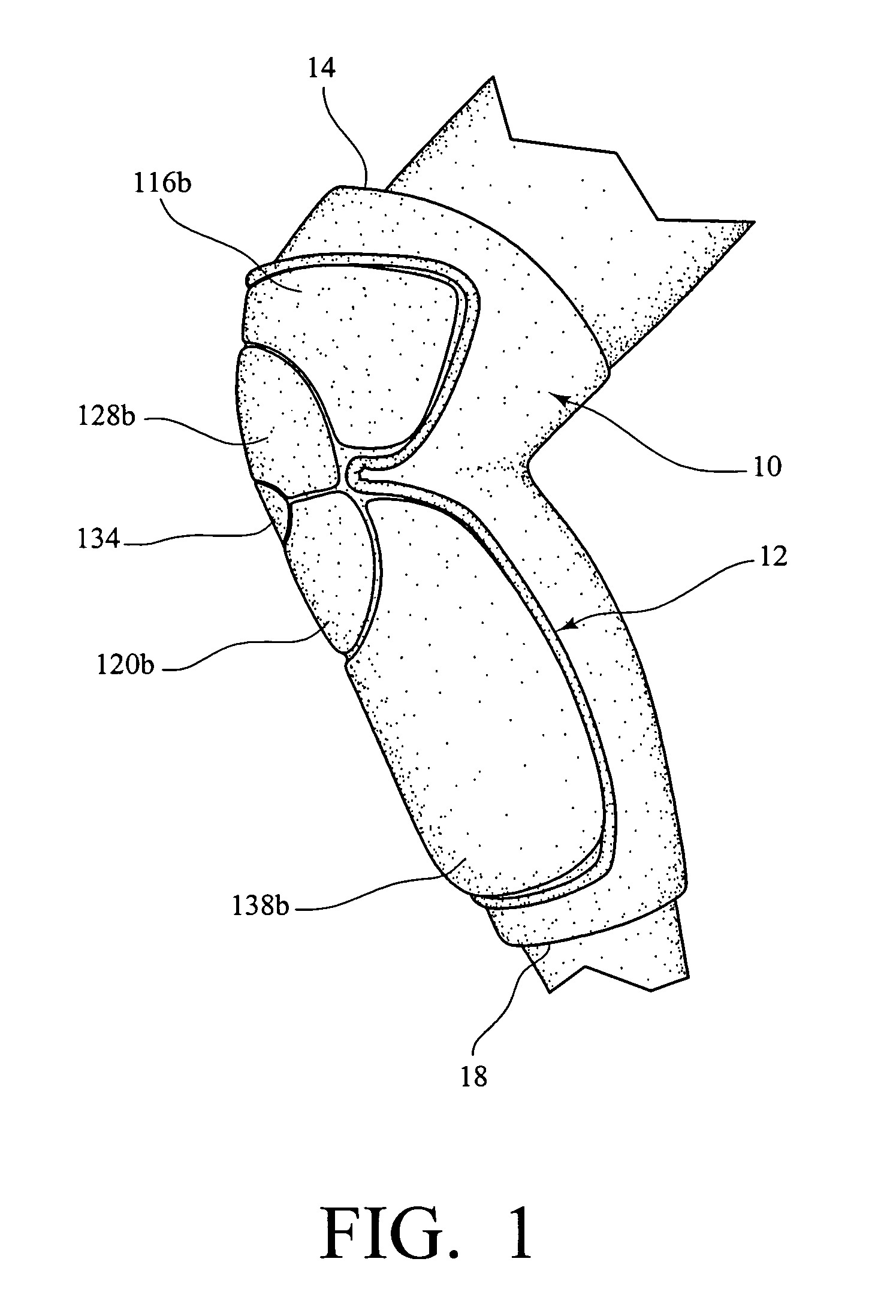
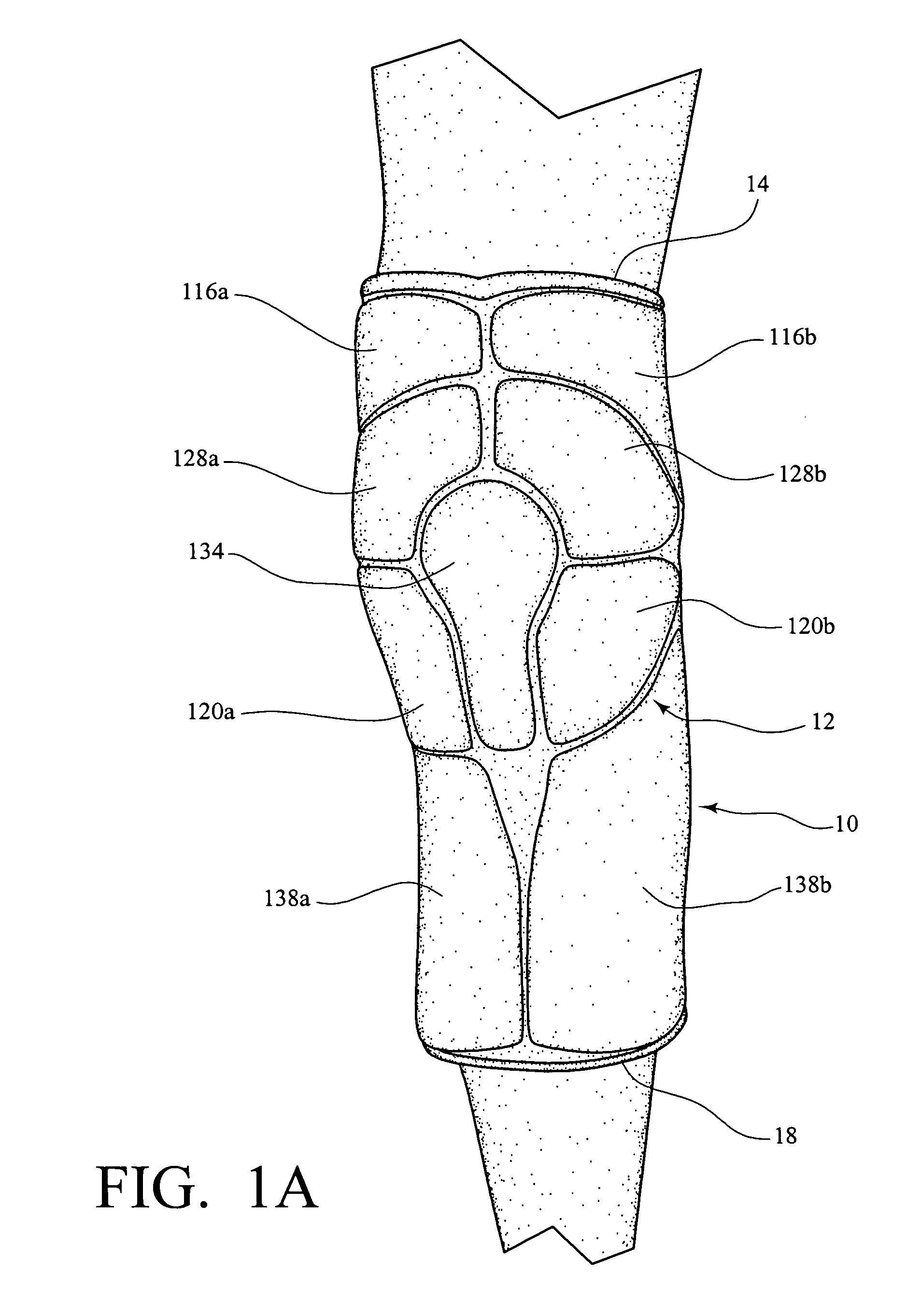
[0014]In the knee protector of the present invention, the knee protector is shown and described for use on the left leg of a user. It is realized that a right knee protector would be a symmetrical reproduction of the left knee.

[0015]As shown in FIG. 1 and FIG. 1A, a knee protector 10 includes a sleeve 12 with a plurality of pads disposed at preselected areas along the outer surface of the sleeve 12. The sleeve 12 is provided with an upper opening 14 to receive the distal femur 16 (FIG. 4) of a leg and a lower opening 18 to receive the proximal tibia 20 (FIG. 4) therein. The padding to be discussed hereinafter may be attached to the inside or the outside of the sleeve 12 and may also include a separate covering (not shown) if desired. The sleeve 12 may include a slit along the backside, (not shown) with fastening and adjustment by any well known fastening devices. Alternatively, sleeve 12 may be an elastomeric material and sized to receive a distal femur 16 in the upper portion there...


PUM


Abstract

A knee protector includes a plurality of pads positioned to cover a patella, a lower portion of the distal femur, the femoral condyles, the upper end of the fibula and an upper end of the proximal tibia with spacings between said pads to accommodate the flexion and extension of the knee when in use from a standing to a squatting position by a wearer.

Description

BACKGROUND OF THE INVENTION[0001]The present invention relates to a knee protector, particularly for use in athletic endeavors. More particularly, the present invention is directed to a knee protector which includes pads at selected areas surrounding the knee cap and are slidably disposed in use from a standing position to a bending condition.[0002]Knee protectors are well known for use by athletes in participation of sports wherein the knee area of the athlete experiences contact with the ground or floor in which the athletic endeavor is occurring. There have been a number of devices proposed for the protection of the knee or the knee cap, but many of these devices either do not provide adequate protection for the knee or knee cap when it comes into contact with the ground or the floor or is extremely cumbersome to the wearer in moving from an upright or standing or moving condition to a bending condition, such as that of a catcher in baseball or softball or a goalie in hockey. For...

Claims


Application Information

Patent Timeline
IPC IPC(8): A41D13/00
CPCA41D13/065A41D13/0153A41D13/0156
Inventor KLEINERT, JAMES M.
Owner HILLERICH & BRADSBY
Why Eureka
Try Eureka