
Buffer

a buffer and insulating body technology, applied in the field of buffers, can solve the problems of difficult to stop the damper main member at an appropriate position to properly fix the projecting length, and it is not possible to increase the projecting length of the damper main member

Active Publication Date: 2006-10-03
NIFCO INC
View PDF7 Cites 29 Cited by
  • Summary
  • Abstract
  • Description
  • Claims
  • Application Information

AI Technical Summary

Benefits of technology

[0008]In order to achieve the objects described above, according to an embodiment of the present invention, a buffer includes a grommet having a tube portion, an attaching portion for attaching the buffer to a member to be attached and an elastic engaging piece projecting inside the tube portion; an engaging member having an engaging step portion provided on an outer surface thereof for engaging the elastic engaging piece to prevent the engaging member from coming out in a counter-insertion direction when the engaging member is inserted i

Problems solved by technology

It is not possible to increase the projecting length of the damper main member from the grommet (refer to Japanese Patent Publication (Kokai) No. 2002-21900).
However, a locking mechanism in which the opening-closing member is locked at a closed position has an over stroke.
Accordingly, when the collar is rotated to fix the projecting length of the damper main member, it may be difficult to stop the damper main member at an appropriate position to properly fix the projecting length.

Method used


Image

  • Buffer
  • Buffer
  • Buffer

Examples


Embodiment Construction

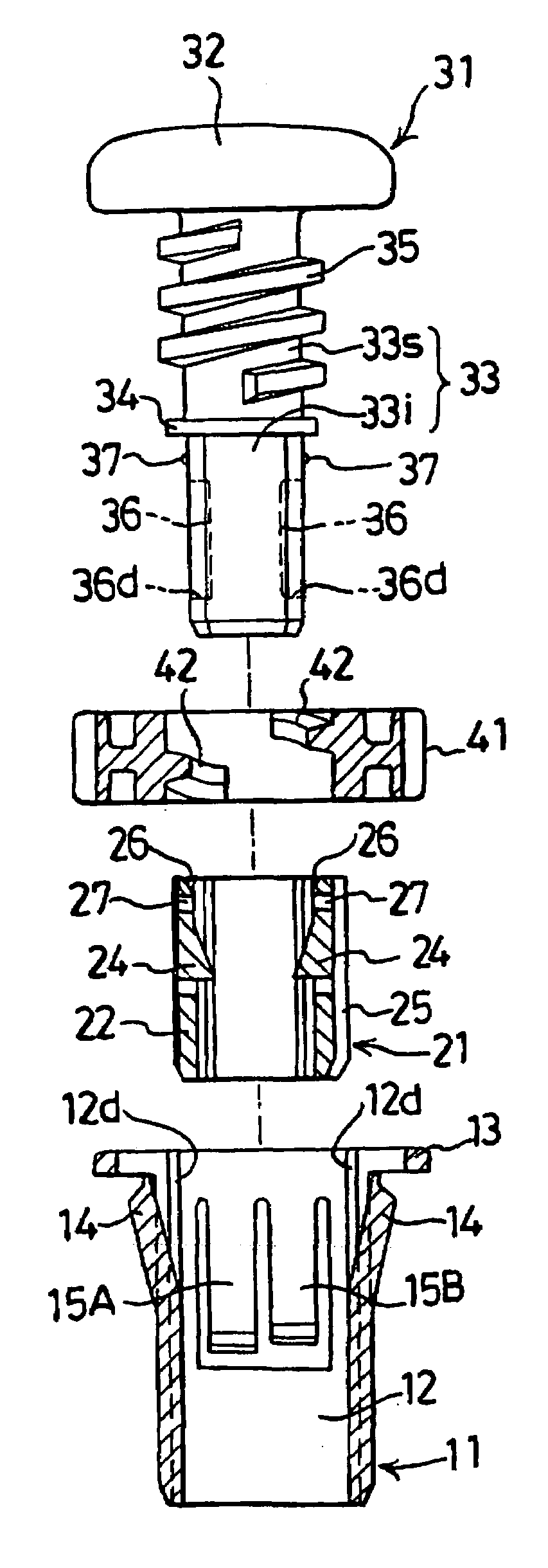
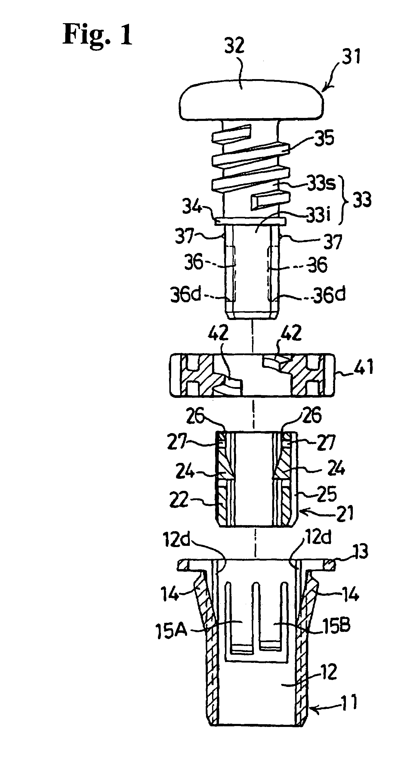
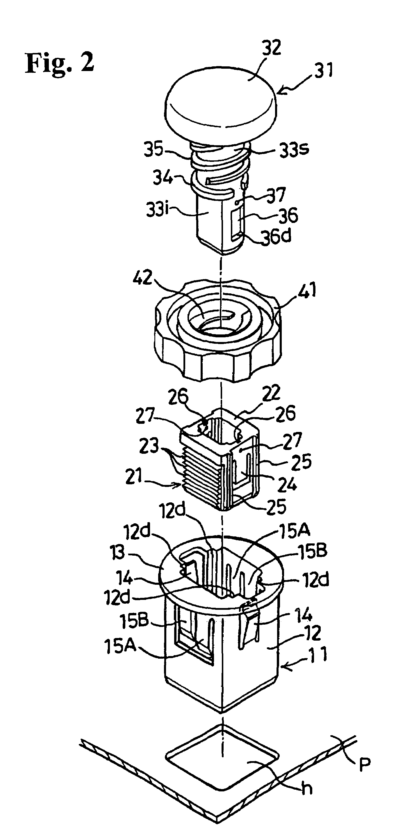
[0020]Hereinafter, preferred embodiments of the invention will be explained with reference to the accompanying drawings. FIG. 1 is a partial sectional front view showing a buffer according to an embodiment of the present invention; FIG. 2 is a perspective view of the buffer shown in FIG. 1; FIG. 3 is a plan view of a grommet shown in FIG. 1; FIG. 4 is a plan view of an engaging member shown in FIG. 1; FIG. 5 is a bottom plan view of a damper main member shown in FIG. 1; FIG. 6 is a plan view of a collar shown in FIG. 1; and FIGS. 7–10 are drawings for explaining a process of attaching the buffer to a panel and a process of adjusting a projecting length of the damper main member.

[0021]In FIGS. 1, 7 and 10, the grommet is shown in sectional views taken along line 1—1 in FIG. 3. In FIGS. 8 and 9, the grommet is shown in sectional views taken along line 8—8 in FIG. 3. In FIGS. 1, 7 and 10, the engaging member is shown in sectional views taken along line 1—1 in FIG. 4. In FIGS. 8 and 9, ...


PUM


Abstract

A buffer includes a grommet having a tube portion, an attaching portion and an elastic engaging piece projecting inside the tube portion; an engaging member having an engaging step portion provided on an outer surface thereof for engaging the elastic engaging piece to prevent the engaging member from coming out in a counter-insertion direction when the engaging member is inserted into the tube portion in an insertion direction; and a damper main member having an abutting portion provided in a middle in a longitudinal direction for abutting against the engaging member when the damper main member is inserted into the engaging member. A projecting length adjustable device is formed for moving the damper main member in the counter-insertion direction and for fixing a projecting length of the damper main member projecting from the grommet.

Description

BACKGROUND OF THE INVENTION AND RELATED ART STATEMENT[0001]The present invention relates to a buffer used as an impact stop member for adjusting a closing position of an opening-closing member such as a hood, trunk cover, or door of an automobile.[0002]As an example of a conventional buffer, an engaging step portion of a damper main member engages an elastic engaging piece of a grommet to maintain a projecting length of the damper main member from the grommet. In a state wherein the projecting length of the damper main member is substantially maximized, the engaging step portion of the damper main member engages the elastic engaging piece of the grommet. Then, the damper main member is pushed into the grommet when an opening-closing member is closed, so that the projecting length from the grommet can be adjusted without rotating the damper main member.[0003]When a collar is rotated to fix the projecting length of the damper main member, the engaging piece (engaging projecting portio...

Claims


Application Information

Patent Timeline
IPC IPC(8): E05F5/02F16F7/00
CPCE05F5/022E05Y2900/546Y10T16/063Y10T16/628Y10T16/625Y10T16/33
Inventor MATSUZAWA, KAZUNARIAWANO, HIRONORI
Owner NIFCO INC
Features
  • Generate Ideas
  • Intellectual Property
  • Life Sciences
  • Materials
  • Tech Scout
  • Unparalleled Data Quality
  • Higher Quality Content
  • 60% Fewer Hallucinations
Learn More