Indirect entry cable gland assembly

a technology of indirect entry and cable gland, which is applied in the direction of machine supports, manufacturing tools, coupling device connections, etc., can solve the problems of costly method of achieving indirect entry, and achieve the effect of reducing large costs and size requirements

Active Publication Date: 2006-10-03
JOY GLOBAL UNDERGROUND MINING LLC
View PDF6 Cites 34 Cited by
  • Summary
  • Abstract
  • Description
  • Claims
  • Application Information

AI Technical Summary

Benefits of technology

[0005]The object of this invention is to provide a cable gland assembly that eliminates the need for welded on terminal chambers on sparking flameproof enclosures.
[0006]Another object of this invention is to eliminate the need to use separate cable glands to enter a welded terminal chamber, and to eliminate the need to use separate insulated bushings between the walls of the welded on terminal chamber and a flameproof enclosure.
[0007]Another object of this invention is to eliminate the large costs and size requirements necessary to meet the current indirect entry requirements of existing standards.

Problems solved by technology

This is a very costly method of achieving indirect entry.

Method used


Image

  • Indirect entry cable gland assembly
  • Indirect entry cable gland assembly
  • Indirect entry cable gland assembly

Examples


Embodiment Construction

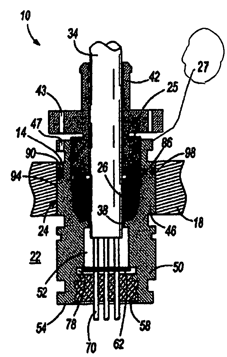
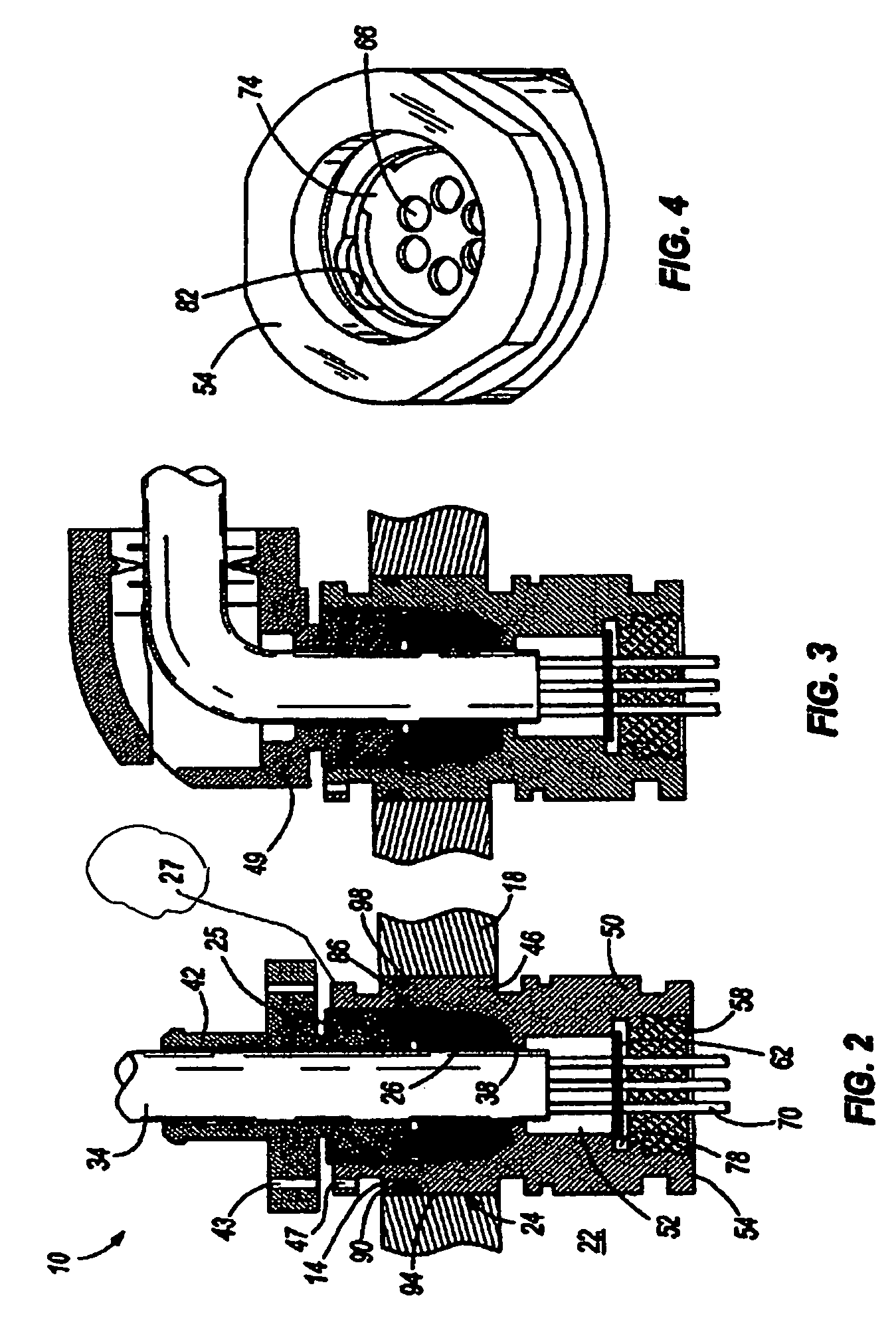
[0013]This invention provides a small indirect entry cable gland assembly 10 capable of being fitted into a bore 14 in the wall 18 of a sparking flameproof enclosure 22 in order to provide an entry for a single conductor or multiple conductor cable 34 into the enclosure 22. The gland assembly 10 is designed to meet the previous Indirect Entry requirements of the International Standards (IEC60079-0 and IEC60079-1 series) for cables with diameters of 5.4 mm to 66.8 mm.

[0014]More particularly, as illustrated in the drawings, the cable gland assembly 10 includes a cable-receiving gland 42 having a gland nut 25, a gland nut housing or stuffing box 24, a grommet 26, an insulator 58 and the cable 34. The stuffing box 24 has an opening 38 there through. The cable-receiving gland 42 is adapted to receive the cable 34. The stuffing box 24 also has a grommet-receiving portion 46 having the grommet 26 therein, the grommet-receiving portion 46 being adjacent the cable-receiving gland 42. More pa...


PUM


Abstract

A cable gland assembly adapted to receive a cable and to pass through an opening in a sparking enclosure wall, the cable gland assembly including a cable-receiving gland, a stuffing box, a grommet, an insulator and a cable. The stuffing box has an opening there through, and a grommet-receiving portion having the grommet therein. The grommet-receiving portion is adjacent the cable-receiving gland. The stuffing box also includes a gas terminal portion filled with gas and adjacent the grommet-receiving portion, and an insulator portion having the insulator therein and being adjacent the gas terminal portion.

Description

BACKGROUND OF THE INVENTION[0001]This invention is directed to an assembly used to permit an electrical cable to enter a flameproof enclosure, and, more particularly, to indirect entry for electrical cables entering sparking enclosures rated greater than 250 watts and 5 amps.[0002]Current indirect entry methods, as shown in FIG. 1, involve installing a chamber 11 on the outside of a flameproof enclosure 13, mounting electrical terminals 15 inside the chamber 11, and providing an insulated bushing 17 for each lead of every cable in the chamber that then enters through the walls of the enclosure 13. This is a very costly method of achieving indirect entry.SUMMARY OF THE INVENTION[0003]This invention provides a set of simple cable gland assemblies that address the requirements of existing standards. This series of assemblies is capable of handling cable diameters from 5.4 mm to 66.8 mm. Each cable passes through a direct entry gland, and then thereafter the cable conductors are separat...

Claims


Application Information

Patent Timeline
Patent Type & Authority Patents(United States)
IPC IPC(8): H02G3/18
CPCH02G3/088H02G3/22Y10T16/05
Inventor DAY, JONATHANCOTHERMAN, JAMESLANDERS, SYLVANMASON, STANLEY J.THOMAS, DAVID G.
Owner JOY GLOBAL UNDERGROUND MINING LLC
Why Eureka
Try Eureka