Switch

a technology of electric switches and contacts, applied in the direction of circuit-breaking switch contacts, circuit-breaking switches, snap-action arrangements, etc., can solve the problems of destroying the switch, and thereby reducing the service life of the switch

Inactive Publication Date: 2006-10-03
MOELLER GEBAUDEAUTOMATION KG
View PDF18 Cites 47 Cited by
  • Summary
  • Abstract
  • Description
  • Claims
  • Application Information

AI Technical Summary

Benefits of technology

[0008]In accordance with the present invention, actuation of the handle in direction of the closing position effects a movement of the support part in direction of the closing position, while the contact bridge is conjointly moved. When a certain intermediate position has been reached, a further movement of the contact bridge is prevented by the locking device, and the contact spring is tensioned as the handle is moved further. When the locking device is released, the contact bridge is thus moved rapidly against the fixed contact by the tensed contact spring, so that contact pressure can be built up very quickly.
[0009]According to another feature of the present invention, the contact mechanism may include a contact slide having a projection, and a contact bridge which is held in the contact slide and includes the contact, wherein the locking mechanism includes a detent interacting with the projection, when the contact mechanism occupies the intermediate position. In this way, the switch is simple in structure. Suitably, the contact slide may be made of an electrically insulating material.
[0010]According to another feature of the present invention, the handle may be constructed for rotation between two end positions along a movement path, wherein the support part is guided in a recess of the contact slide, and a bar is provided for connecting the support part with the handle. In this way, a rotational movement of the handle is converted in a simple manner into a translational movement, with the support part being guided in the contact slide.
[0011]According to another feature of the present invention, the release mechanism may include a lobe formed on the handle, wherein the detent is configured as a swingable angle lever having one arm interacting with the lobe, and with another arm formed with a hook-shaped end for interacting with a projection of the contact slide to maintain the contact mechanism in the intermediate position and maintaining the contact spring under tension. In this way, a very secure form-fitting locking of the movement of the contact slide is realized. The use of an angle lever permits hereby a very compact configuration of the detent which can easily be released by the lobe of the handle.
[0013]According to another feature of the present invention, the locking mechanism may be constructed to inhibit a movement of the contact slide, when the contact slide moves in direction of the closing position and the handle is moved by about a third of the movement path, so that a further movement of the handle results only in a displacement of the support part in opposition to the force of the contact spring, whereby the locking mechanism can be released when the handle is moved approximately by half of the movement path.

Problems solved by technology

The closing speed of the contact bridge is hereby relatively small and the buildup of a sufficient contact pressure during closing of the contacts is relatively slow.
This slow buildup of contact pressure poses a problem, when greater currents and higher inductive loads are involved, because switches of this type have then a tendency to fuse the contacts, resulting eventually in a destruction of the switch.

Method used


Image

  • Switch
  • Switch
  • Switch

Examples


Embodiment Construction

[0021]Throughout all the Figures, same or corresponding elements are generally indicated by same reference numerals. These depicted embodiments are to be understood as illustrative of the invention and not as limiting in any way. It should also be understood that the drawings are not necessarily to scale and that the embodiments are sometimes illustrated by graphic symbols, phantom lines, diagrammatic representations and fragmentary views. In certain instances, details which are not necessary for an understanding of the present invention or which render other details difficult to perceive may have been omitted.

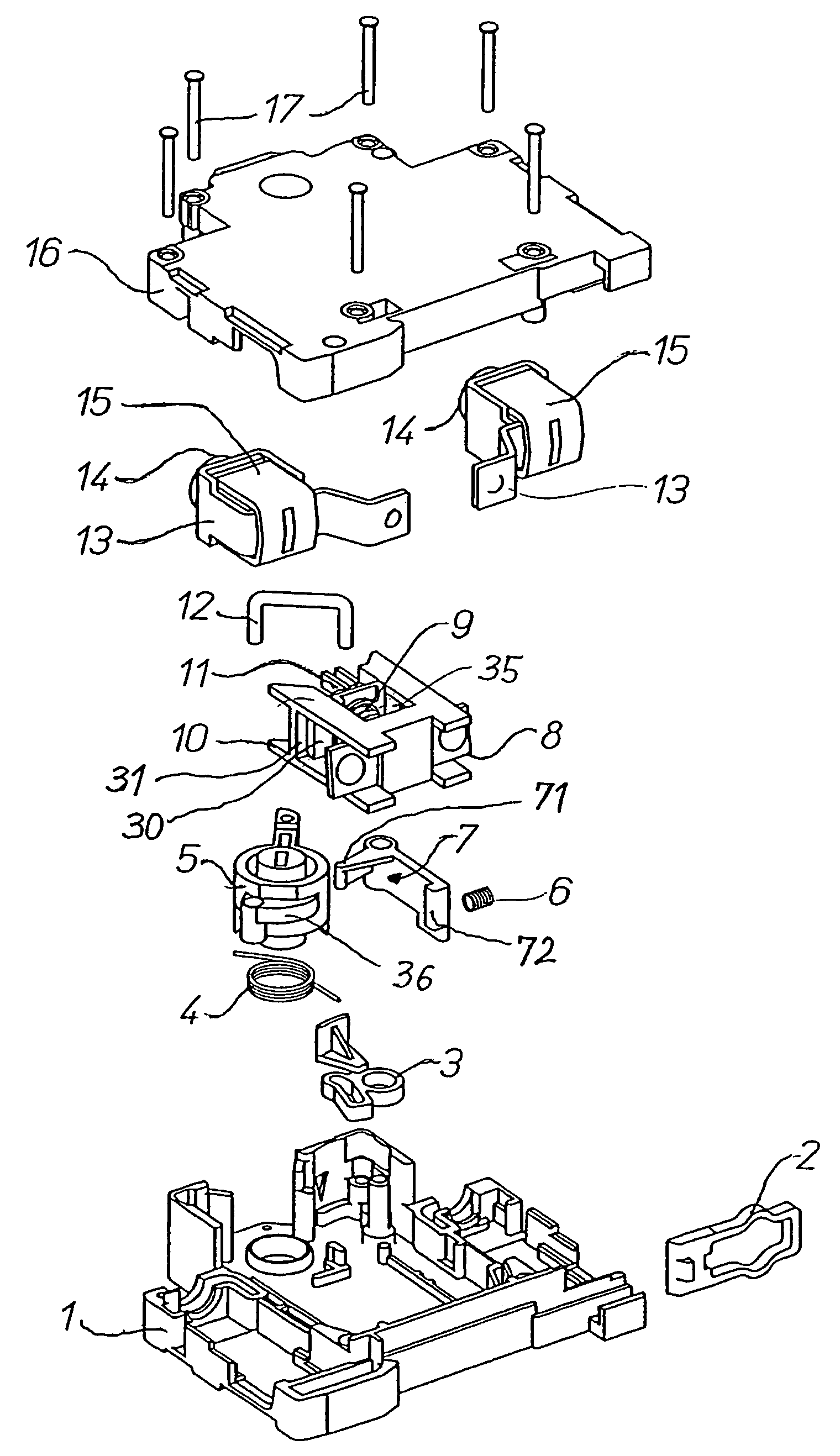
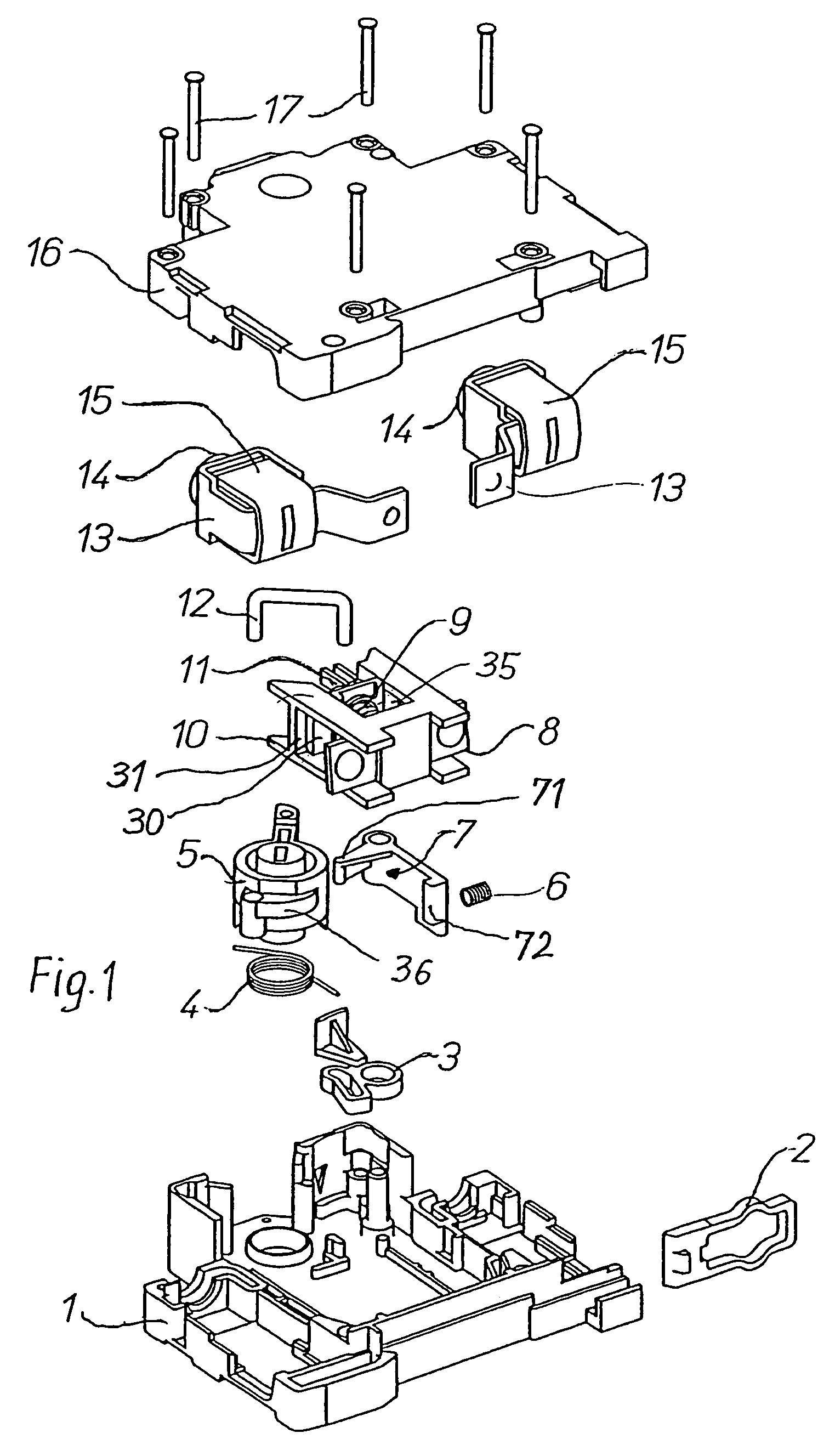
[0022]Turning now to the drawing, and in particular to FIG. 1, there is shown an explosive illustration of a switch according to the invention, having a bottom shell 1 in which a contact slide 10 is guided which holds a contact bridge 8. The bottom shell 1 interacts with a top shell 16 to form together a casing, with both shells 1, 16 being connected with one another via faste...


PUM


Abstract

A switch includes a contact mechanism having at least one contact and defining a longitudinal axis. Actuation of a handle moves the contact mechanism transversely to the longitudinal axis between an open position and a closed position in relation to at least one fixed contact, whereby a contact spring loads the contact mechanism to seek the closed position. A support part is operatively connected to the handle and forms an abutment for support of the contact spring. The support part is moveable relative to the contact mechanism. Operated by the handle is a locking mechanism which is constructed to hold the contact mechanism in an intermediate position between the open and closed positions to maintain the contact of the contact mechanism at an electrically insulated distance from the fixed contact. A release mechanism interacts with the locking device for releasing the contact mechanism to move to the closed position.

Description

CROSS-REFERENCES TO RELATED APPLICATIONS[0001]This application claims the benefit of prior filed U.S. provisional Application No. 60 / 505,311, filed Sep. 23, 2003, pursuant to 35 U.S.C. 119(e), the disclosure of which is incorporated herein by reference.[0002]This application also claims the priority of Austrian Patent Application, Serial No. A 1504 / 2003, filed Sep. 23, 2003, pursuant to 35 U.S.C. 119(a)–(d).BACKGROUND OF THE INVENTION[0003]The present invention relates, in general, to the field of electric switches.[0004]Nothing in the following discussion of the state of the art is to be construed as an admission of prior art.[0005]European Patent Publication No. EP 1 054 421 discloses a switch which has a toggle joint system for connecting a handle with a contact bridge, whereby the joint of the toggle joint system is guided in a slot and is acted upon by a spring. The slot has a substantially triangular configuration for passage of the joint and is thus relative complicated in st...

Claims


Application Information

Patent Timeline
Patent Type & Authority Patents(United States)
IPC IPC(8): H01H5/00H01H21/42H01H71/52H01H73/04
CPCH01H21/42H01H71/521H01H73/045H01H2300/048H01H21/36H01H71/50H01H71/52H01H73/00H01H77/00
Inventor SCHMID, JOHANNES
Owner MOELLER GEBAUDEAUTOMATION KG
Why Eureka
Try Eureka