Concealed safety lighting device

a safety lighting and concealed technology, applied in the field of alternative, can solve the problems of power failure lighting, providing an unremarkable and concealed appearance of a safety light, etc., and achieve the effect of convenient installation and low manufacturing cos

Inactive Publication Date: 2006-10-10
BARTON MR ROBERT A
View PDF18 Cites 92 Cited by
  • Summary
  • Abstract
  • Description
  • Claims
  • Application Information

AI Technical Summary

Benefits of technology

[0036]A still further objective of the present invention is to provide safety lighting in the darkness regardless of the state and availability of AC power.
[0037]Another object of the present invention is to provide nighttime lighting when AC power is available for use as a nightlight in a concealed, unobtrusive manner allowing for a more child safe, non-removable night lighting device to take the place of the removable incandescent devices

Problems solved by technology

It provides night lighting using AC power when available, and it also provides power failure lighting when AC power is not available.
The

Method used


Image

  • Concealed safety lighting device
  • Concealed safety lighting device
  • Concealed safety lighting device

Examples


Embodiment Construction

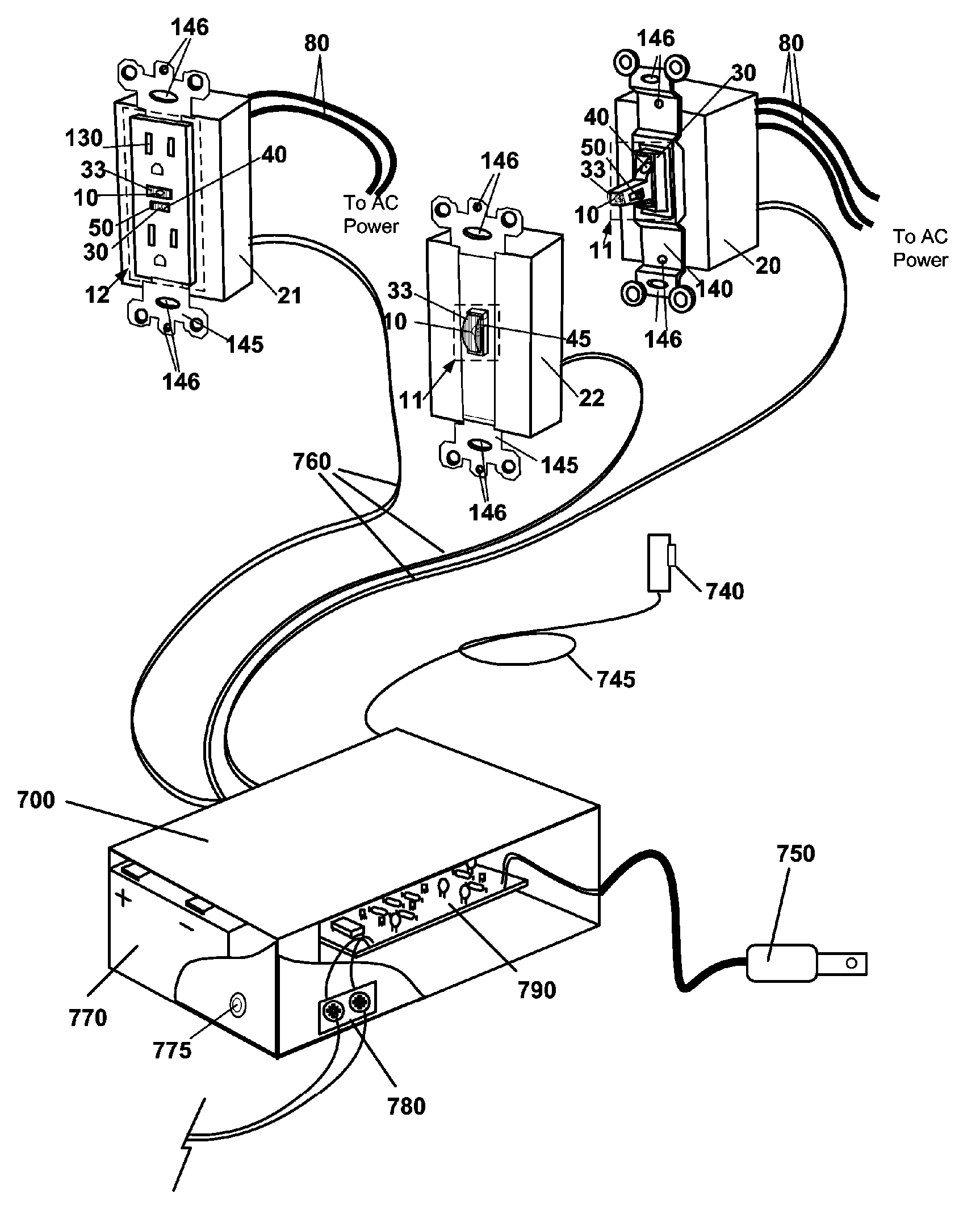
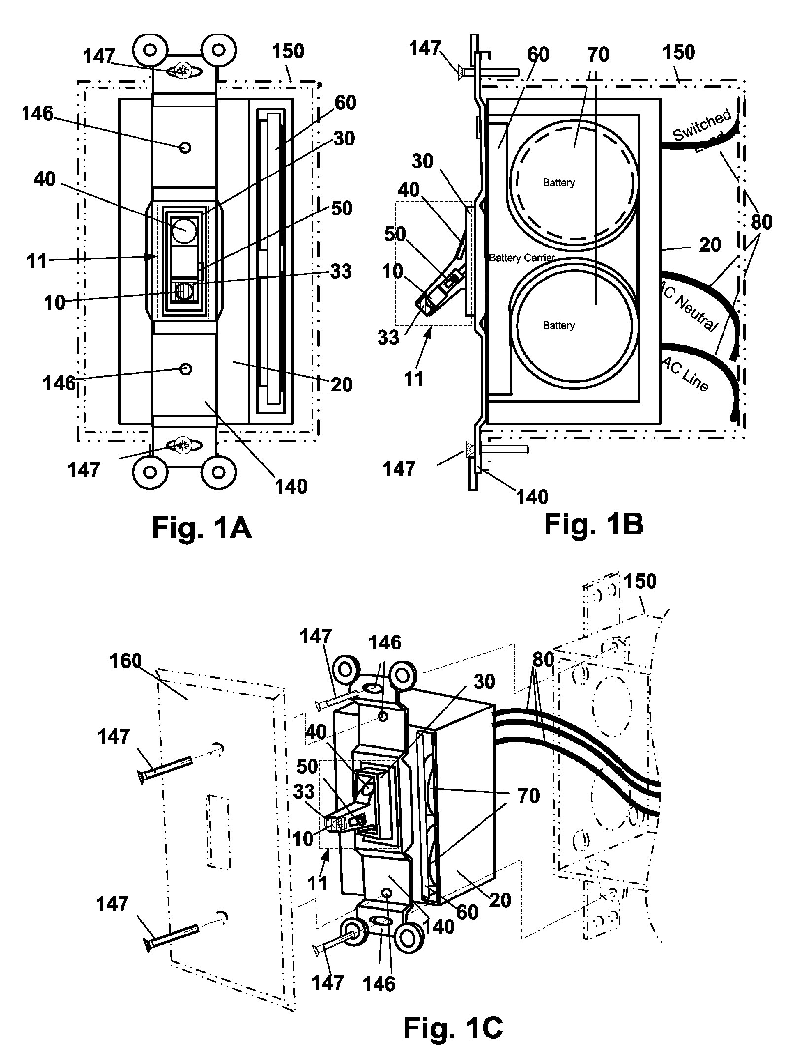
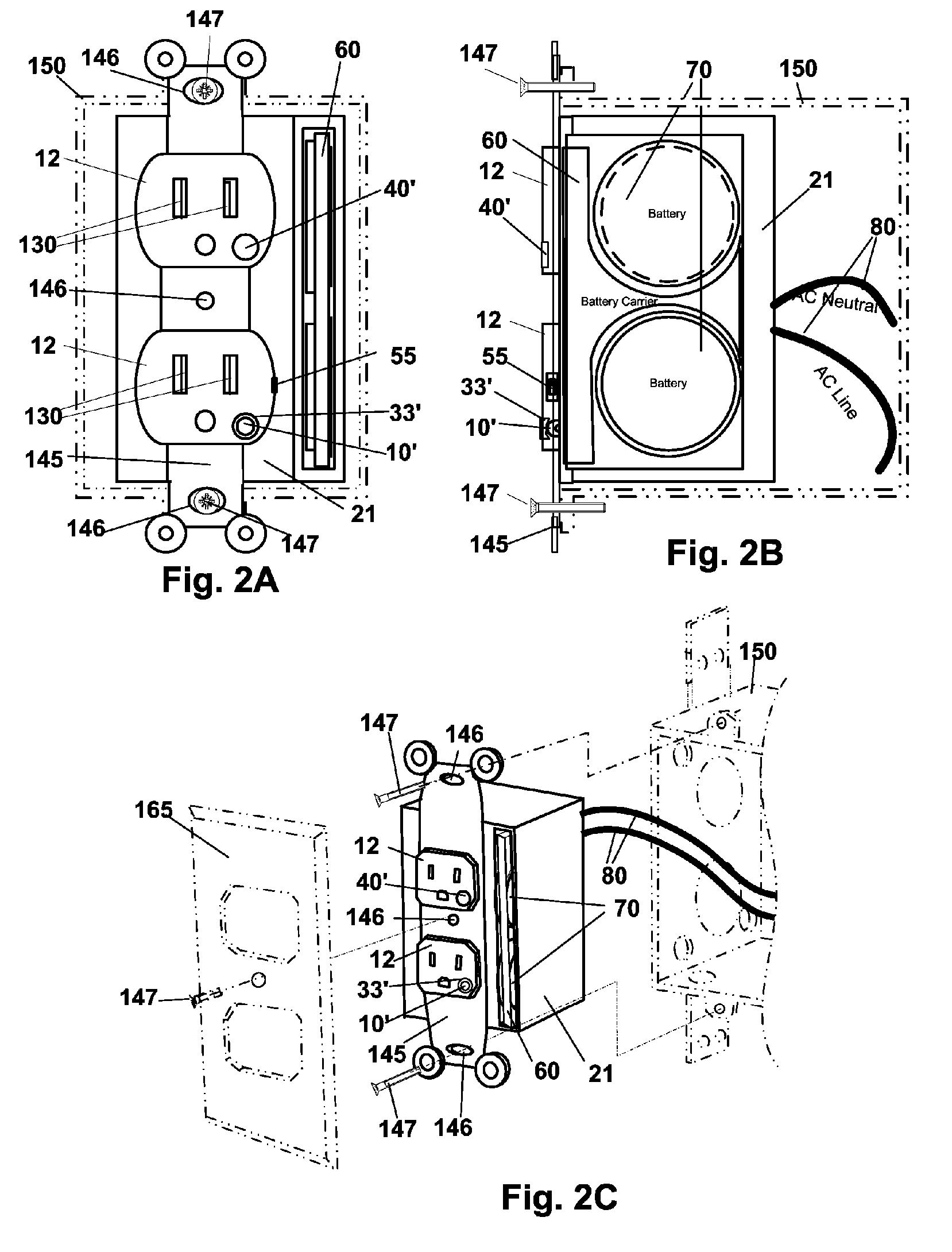
[0085]Turning now descriptively to the drawings, in which similar reference characters denote similar elements throughout the several views, FIGS. 1A through 3 illustrate two implementations of the concealed safety lighting device of the present invention using classic styles of switches and outlets. Other implementations for the concealed safety lighting device using decorative or Decora wiring devices are shown in FIGS. 5A through 6C depicting how substantially similar their structure and function are in allowing them to conceal a safety lighting device. FIG. 7 shows a multi-unit whole house embodiment of the present invention.

[0086]FIGS. 1A through 1C show the safety light source 10 embodied in the normally exposed area 11 of the switch actuator handle in such a way as to allow the light to escape from the actuator handle through the light transmission means 33 which remains visible after installing the switch cover plate 160. It also illustrates one method of installing the alte...


PUM


Abstract

A concealed safety light is described where the light source is integrated and mounted into a switch or power outlet wiring device form factor (20,21,22) to replace conventional electric wiring devices. The light source (10) is controlled by a power and control circuit (90, 790) that derives power from the primary power supply or an alternate power supply. The circuit can detect light levels and turn on the light source when it is dark and also detect power failures to turn on the safety light in the event of a power failure using the alternate power supply The safety light is also capable of responding to an alarm condition from other systems. The resulting safety light is conceyaled in a standard wiring junction box and trimmed with a wall cover plate in the same way as conventional electric wiring devices, allowing it to be concealed while in plain view and provide safety lighting in a variety of ways including power failure, night light and alarm conditions.

Description

CROSS REFERENCE TO RELATED APPLICATIONS[0001]This application is a continuation-in-part of application Ser. No. 10 / 249,723 filed on May 3, 2003, now U.S. Pat. No. 6,805,469.BACKGROUND OF INVENTION[0002]The present invention relates generally to alternate safety lighting devices and, more specifically, to a safety lighting device that is combined with standard wall switches and power outlets such that they are unobtrusive in their appearance while capable of providing nighttime lighting during power failures.DESCRIPTION[0003]Emergency lighting devices are typically installed in such obvious ways that they interfere with visible design and decor of a living space or workspace. This often affects a person's decision on whether or not to install them. Making the emergency lighting device inconspicuous will result in more installations and thus safer homes and workplaces.[0004]Some amount of light is necessary during the night time to allow people to move about safely. The reduction in s...

Claims


Application Information

Patent Timeline
IPC IPC(8): F21V19/04F21S9/02H01R13/717H02G3/20H02J9/02
CPCF21S9/022H02G3/20H02J9/02F21Y2101/02H01R13/717H01R13/7175H01R24/76H01R2103/00Y10S362/802F21Y2115/10
Inventor BARTON, ROBERT A
Owner BARTON MR ROBERT A
Why Eureka
Try Eureka