One person drywall machine

a drywall machine and one person technology, applied in the field of drywall panel installation machines, can solve the problems of requiring additional equipment and/or personel, and achieve the effects of low weight, affordable purchase and use, and low manufacturing cos

Inactive Publication Date: 2006-06-08
STEWART CHARLES EDGAR
View PDF7 Cites 2 Cited by
  • Summary
  • Abstract
  • Description
  • Claims
  • Application Information

AI Technical Summary

Benefits of technology

[0010] An additional object is to provide a drywall machine that is portable and light weight enough that a single worker can move it to the job, set it up, and use it without assistance.
[0011] A still further object is to provide a drywall machine that is economical in cost to manufacture, thereby making it affordable to purchase and use.

Problems solved by technology

That is a machine that fulfills all the needs of the art. ie. many have the ability to raise the panel to the necessary height, but become unstable and subject to tipping in the process.
Also, even the ones that maintain stability offer no means of getting the worker to the necessary height to install the nails or screws to complete the installation, Thereby requiring additional equipment and / or personel.

Method used


Image

  • One person drywall machine
  • One person drywall machine
  • One person drywall machine

Examples


Embodiment Construction

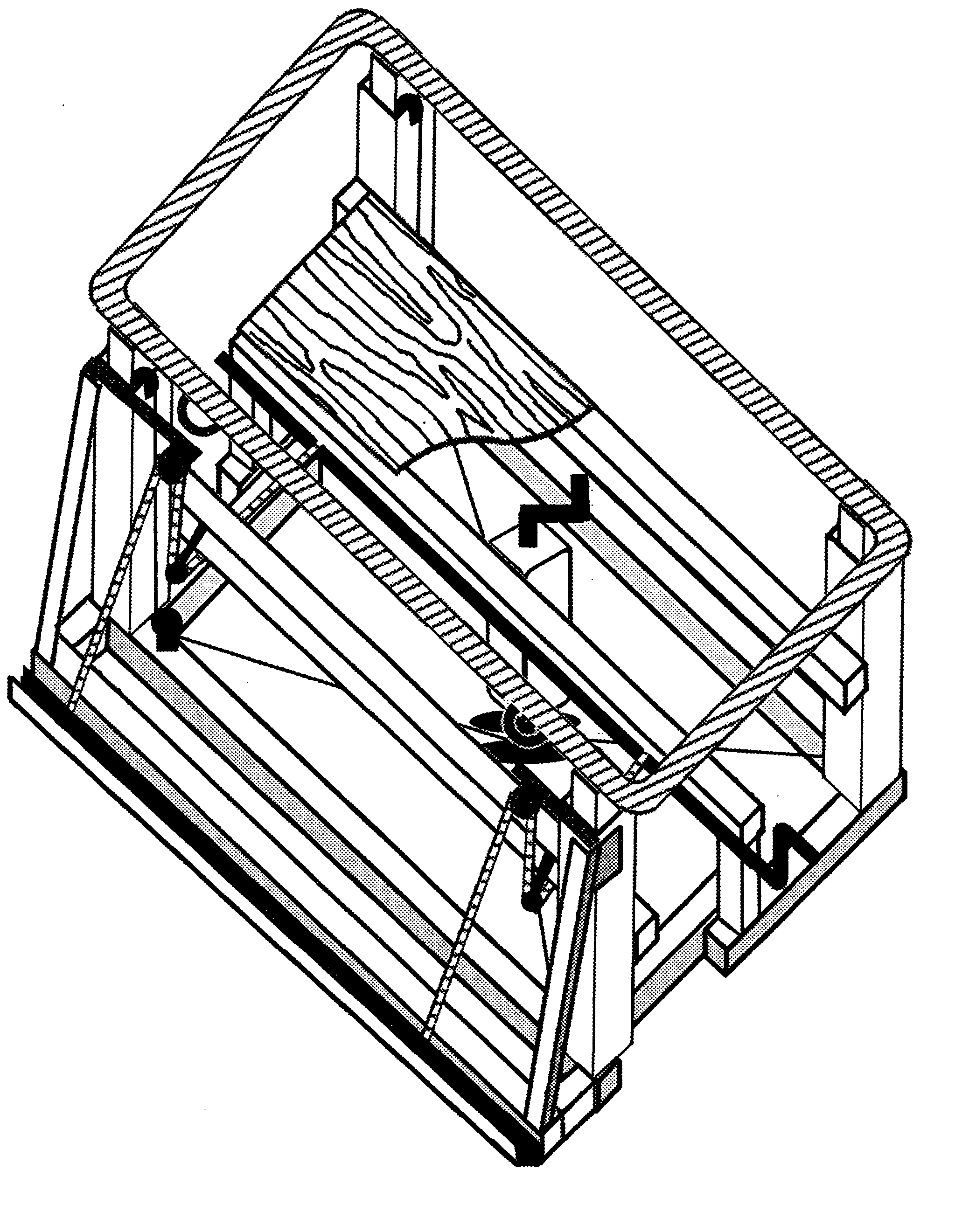
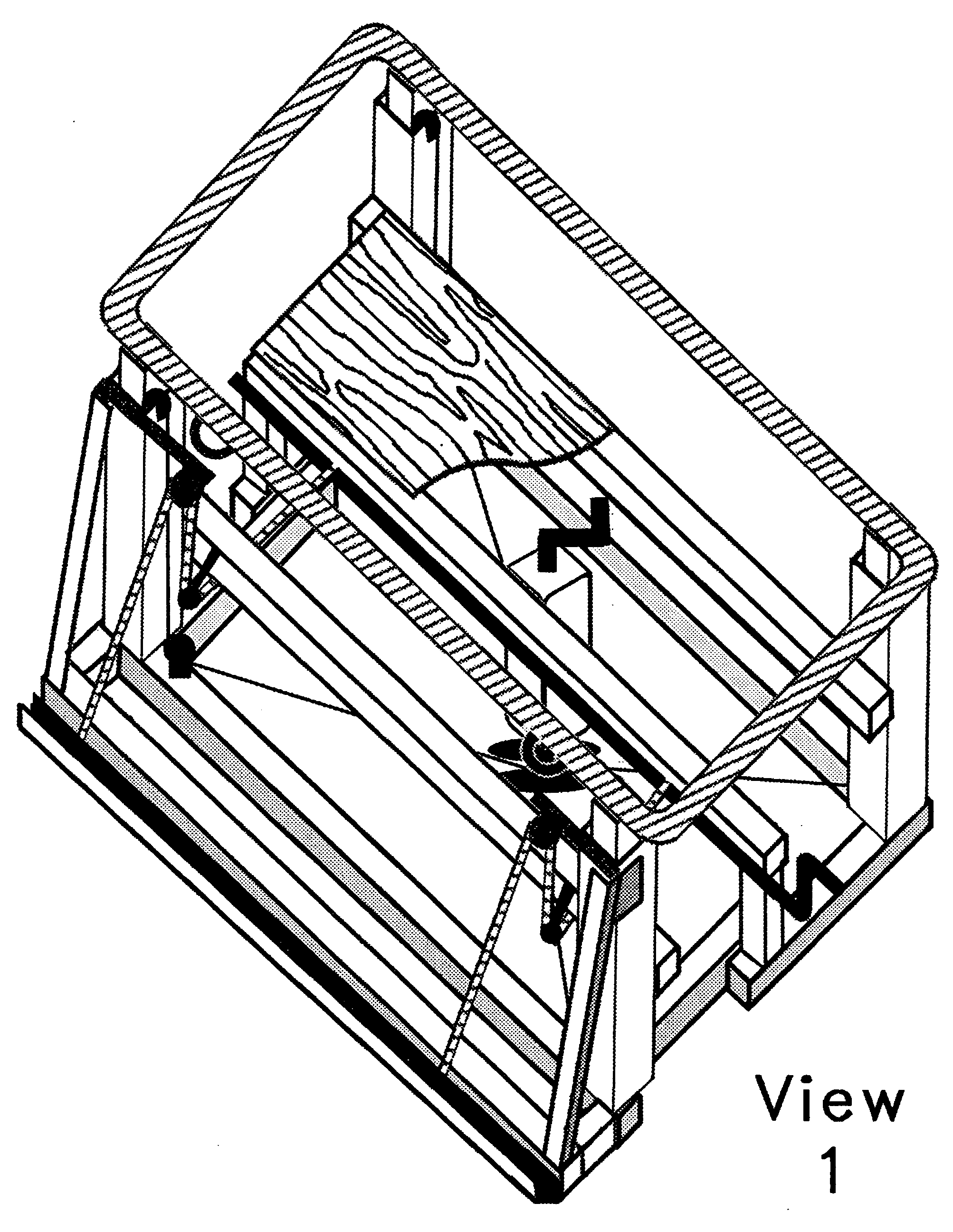
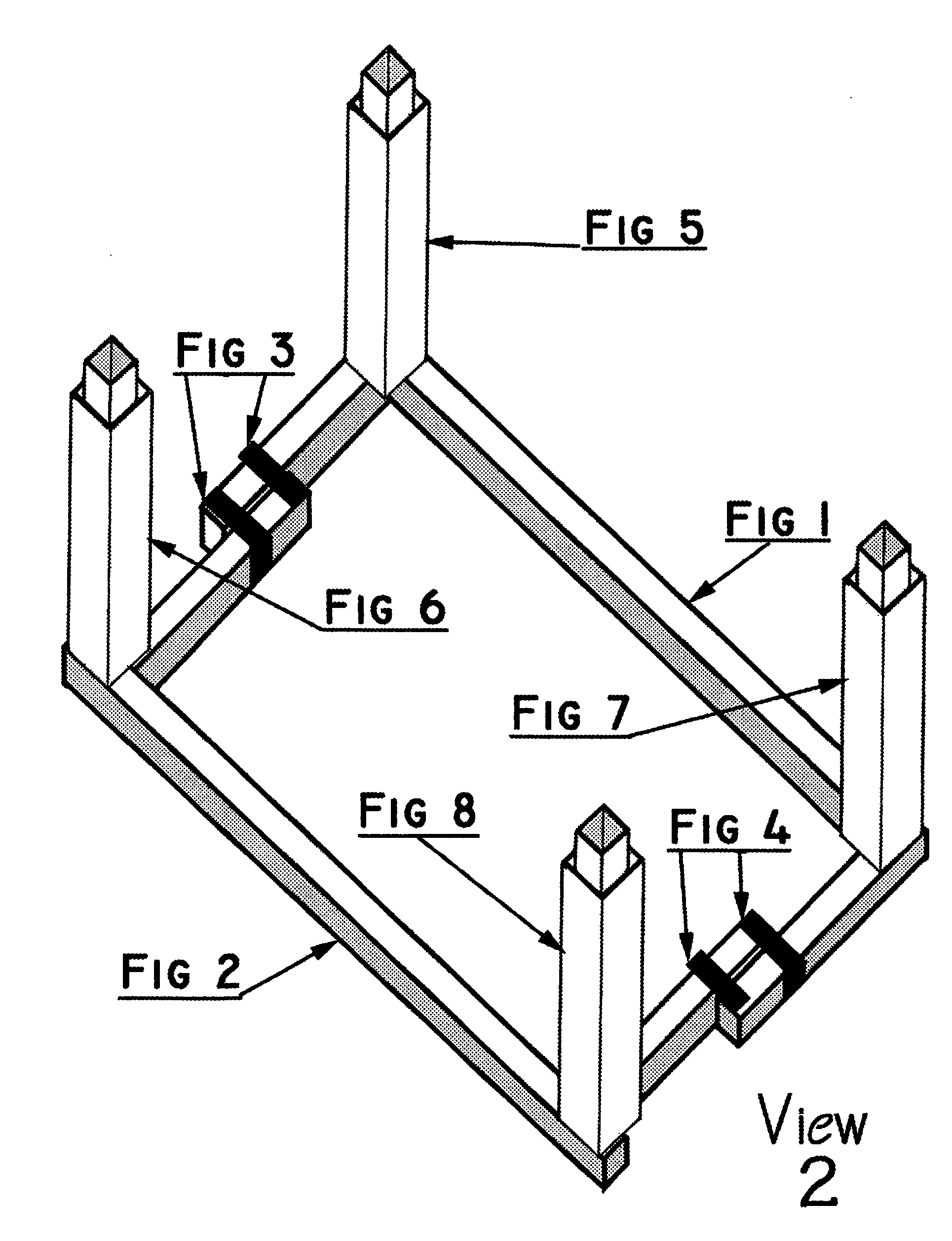
[0064] The “One Person Drywall Machine” construction consists of a generally rectangular “Frame Base” of hollow steel tubing approximately 3 ft. by 4 ft. Consisting of a “Rear Bottom Frame Section” (See View 2—FIG. 1), a “Front Bottom Frame Section” (See View 2—FIG. 2), a “Left Frame Expansion Joint” (See View 2—FIG. 3), and a “Right Frame Expansion Joint” (See View 2—FIG. 4), so constructed as to be easily contracted to approximately 2 ft. by 4 ft. (See View 2—FIG. 3 and FIG. 4, and View 6—FIG. 3 and FIG. 4) so as to provide easy access through doorways. Said “Frame Base” is mounted on common casters (not shown) at each corner to facilitate mobility of machine. Attached to the top of each corner of this frame is a “Telescoping Post” extending vertically. These posts consist of two or more sections of hollow steel tubing, one inside the other, (See View 2—FIG. 5, FIG. 6, FIG. 7, and FIG. 8 and View 7 Details of post), to allow vertical extension to ceiling height. Vertical extension...


PUM


Abstract

This device is a complete drywall installation machine and finishing platform. It consists of a simple mechanism that raises the sheathing from floor level to the top platform of the machine where it is then raised to the rafters and held securely in place for attachment, by stepping on to the elevated platform to be at the perfect working height to apply fasteners. In it's auxiliary configuration this machine also lifts and places wallboard into position on wall studs for attachment with absolute minimum effort. This machine is portable, mobile, and light weight enough to allow one worker to install drywall up to 12 ft. in lenght to walls and/or ceilings with less effort than is normally exerted by each of 2 or more workers. Once the installation is complete the machine serves as a mobile work platform to do the taping and finishing. The entire process is executed by one worker and requires no addional equipment such as ladders, stilts, or support devices.

Description

CROSS-REFERENCE TO RELATED APPLICATIONS [0001]“Not Applicable”STATEMENT REGARDING FEDERALLY SPONSORED RESEARCH OR DEVELOPMENT [0002]“Not Applicable”REFERENCE TO SEQUENCE LISTING, A TABLE, OR A COMPUTER PROGRAM LISTING COMPACT DISK APPENDIX [0003]“Not Applicable”BACKGROUND OF THE INVENTION [0004] This invention relates generally to hoisting and positioning apparatuses (414 / 10 Flat wall or ceiling member manipulating means: This subclass is indented under subclass 10. Apparatus wherein the means is designed to reorient or reposition a unit of material having a flat surface and which, when secured in place, will form a part or all of the wall or ceiling portion of a building.) and more specifically it relates to a drywall panel installation machine, which provides a mechanism to lift a drywall panel and hold it in place against ceiling rafters or wall studs to be attatched thereto by one person, and a working platform for said person. [0005] While there are various conventional hoistin...

Claims


Application Information

Patent Timeline
Patent Type & Authority Applications(United States)
IPC IPC(8): E04G21/14
CPCE04F21/1811
Inventor STEWART, CHARLES EDGAR
Owner STEWART CHARLES EDGAR
Why Eureka
Try Eureka