Light Bulb Changing Device

Active Publication Date: 2020-07-16
THE HOLMS GRP
View PDF0 Cites 1 Cited by
  • Summary
  • Abstract
  • Description
  • Claims
  • Application Information

AI Technical Summary

Benefits of technology

The invention is a light bulb changing tool that can be easily adapted to various sized and shaped light bulbs. The device can be operated from either the distal or proximal end and has a reduced actuation force, making it easier for older or weaker individuals to use. It is simple and economical to manufacture. The device also controls the amount of torque applied to the light bulb, ensuring proper installation and removal without causing damage to the glass bulb.

Problems solved by technology

One such problem is accessibility.
Another problem is the adjustability of the handle to reach light bulbs at varying distances.
Another problem is light bulbs are subject to separation from their metal base if the user applies too much torque while installing.
Another problem is not providing adequate assurance that the device will hold the bulb without the chance of dropping the bulb and breaking it.
Another problem is that many light bulb changing devices do not provide the ability for the user to actuate the mechanism from both the proximal (bottom handle) or distal (upper gripping end) ends.
The patent teaches that the rods are adjustable to reach light bulbs at different heights, but the mechanism to lock the rods at a desired height is cumbersome.
Therefore, the user can only adjust the rod at certain heights, which is burdensome if the light bulb is at a height that does not correspond to any of the positions available on the rod.
Said fingers are limited in adjustment range to a single size bulb.
Further, the mechanism to actuate the gripping fingers is only actuatable by the user from the proximal end opposite the fingers, which creates difficulty inserting a replacement bulb into the fingers, due to the necessity of opening and closing the fingers from the proximal end.
The means for closing and opening the fingers is by use of a thumb nut and feed screw only actuatable at the distal, or finger end of the device thereby rendering actuation of the fingers at an elevated location difficult or impossible.
The fingers are only actuatable at the distal, or finger end of the device, thereby rendering actuation of the fingers at an elevated location difficult or impossible.
Further, the geometry of the fingers and collar do not provide a large range of adjustment.
The problem which this invention does not solve is that the grappling means or gripping fingers, when in the most extended position, have very low gripping force due to the very small amount of leverage applied to the fingers.
Although this light bulb changer allows the user to bend the arm to engage light bulbs at different angles, the light bulb changer does not allow the user to adjust the handle to different heights.
Further, the light bulb changer taught by Negley does not allow the user to adjust the mechanism to fit differently sized light bulbs.
However, the device taught by Maki, by having a fixed rod, does not allow the user to adjust the rod to different heights.
This is disadvantageous to the user, because the cup is not adjustable to engage different sized light bulbs.
In addition, the increasingly prevalent use of aluminum instead of brass in the base of the bulb has tended to increase problems caused by the bending or other malfunction of the base.
A common fault is that the bond between the glass envelope and the base is broken.
Grudgefield identifies that a twisting force is necessary to screw or unscrew the bulb, and he identifies the problem of breaking bulbs or separating them from their Edison screw base but he does not identify a solution of controlling the torque applied to the bulb to prevent such an occurrence.
DuBois also identifies the need for friction between the fingers and the bulb but does not identify a solution to control the torque of the fingers.
The patent does disclose the use of a chain to be pulled by the operator to grip the bulb such that the operator must pull the chain and turn the device to screw or unscrew the bulb simultaneously which is a difficult operation for some individuals.
If the adjustment is made incorrectly then the sliding collar must be readjusted, possibly multiple times. This presents a cumbersome process for removing a light bulb.
Further, the disclosed device is unduly complicated creating a very expensive execution.

Method used


Image

  • Light Bulb Changing Device
  • Light Bulb Changing Device
  • Light Bulb Changing Device

Examples


Embodiment Construction

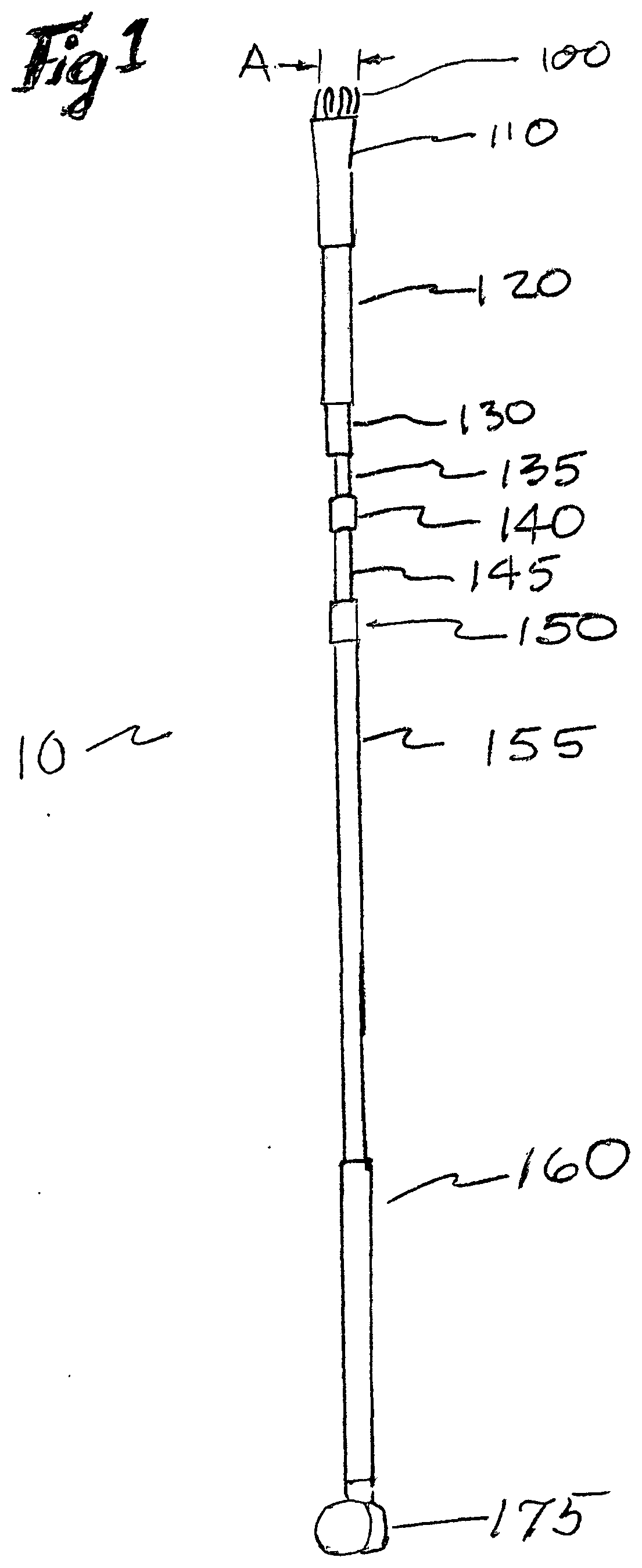
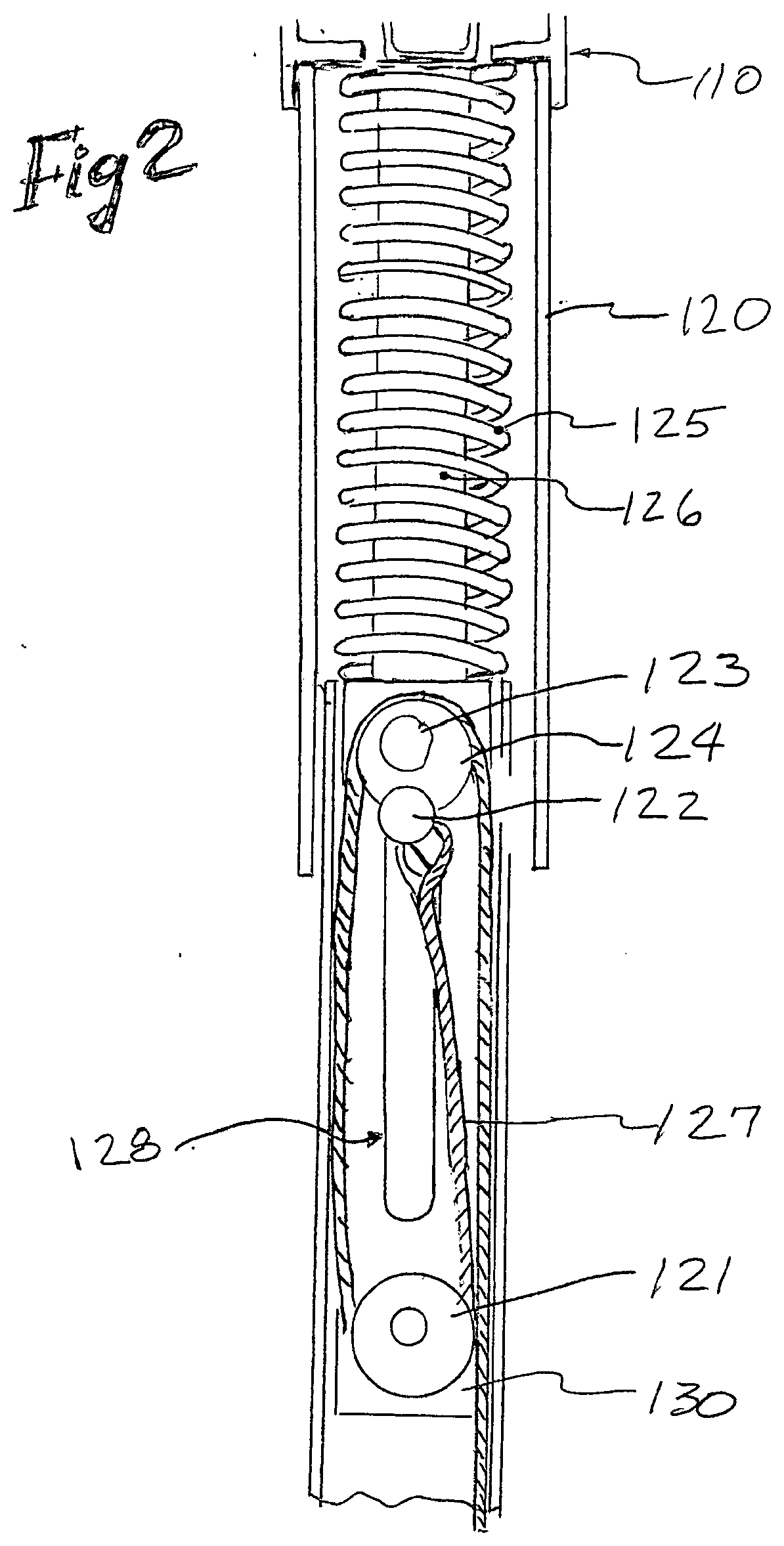
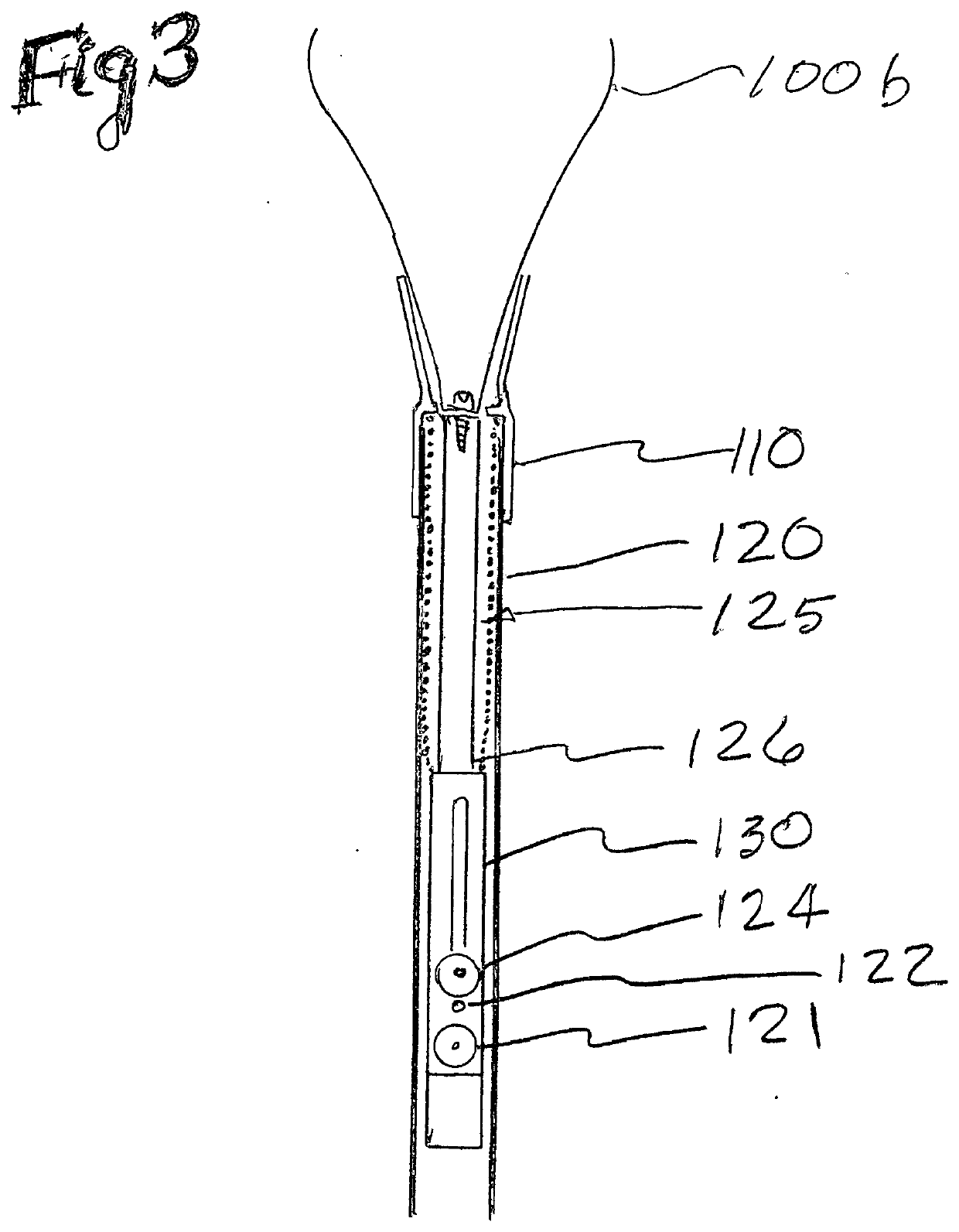
[0034]FIG. 1 shows, at a distal end of the disclosed light bulb changer, from here on to be abbreviated to lbc, flexible fingers 100, said fingers having a preferred curvilinear shape, said fingers shown in the fully retracted position, dimension A, a horn 110 which helps to control the position of the at least two flexible fingers, a tube 120 which encases a compression spring which is shown in FIG. 2. Also shown is a pulley housing 130, a small diameter extension tube 135, a small bushing 140 which provides a low friction sliding surface between said metal tubes such that metal does not slide against metal, an intermediate diameter extension tube 145, a large bushing 150 used to prevent metal-to-metal sliding, large diameter extension tube, said more than one extension tubes and said bushings combine to provide a set of at least two telescoping extension tubes to allow the user to expand or contract along an axial direction to provide for a greater or lesser axial length for the p...


PUM


Abstract

A light bulb changing device with expandable fingers which can grasp all light bulbs within a size range between 1 inch and 6 inches diameter and all shapes of light bulbs including incandescent, compact fluorescent and LED having a screw thread base. The disclosed device is extendable to allow a person to install and remove light bulbs from an elevated ceiling without need for climbing a ladder. The device provides for a user to controllably expand the fingers to insert or remove a bulb at both the proximal (bottom)and distal (Ceiling) ends of the device so that a user can reach up to the ceiling, open the fingers to grasp the bulb using the proximal actuation, remove it, bring it down to reachable level, remove the used bulb using the distal actuation, insert a new bulb using the distal actuation, elevate the bulb to the ceiling screw it into the socket and using the proximal actuation open the fingers to complete the job. The disclosed device controls the torque with which the fingers grasp the bulb to prevent separation of the glass bulb from the metal base.

Description

FIELD OF THE INVENTION[0001]The present invention relates to a device which may be used to change a light bulb which is beyond the reach of a person. More specifically, the present invention relates to a mechanical device designed to remove and replace a full range of light bulb sizes having a typical Edison screw base.BACKGROUND OF THE INVENTION[0002]Numerous light bulb removal tools have been disclosed, manufactured and sold which alleviate the problems associated with replacing light bulbs from remote locations. One such problem is accessibility. Overhead lights are typically positioned on or in a ceiling of a room. Another problem is the adjustability of the handle to reach light bulbs at varying distances. Additionally, light bulbs of vastly different sizes and shapes are available. Another problem is light bulbs are subject to separation from their metal base if the user applies too much torque while installing. A typical light bulb is tightened to a torque of approximately be...

Claims


Application Information

Patent Timeline
IPC IPC(8): H01K3/32B25B9/00
CPCB25B9/00H01K3/32H01J9/006
Inventor O'BANION, MICHAEL LESTERLEUKING, LOWELL DEANHUSTON, TODD JAMESMISKEL, HUGH
Owner THE HOLMS GRP
Why Eureka
Try Eureka