Stripping process with disproportionately distributed openings on baffles

a technology of baffles and openings, applied in lighting and heating apparatus, furnace types, furnaces, etc., can solve the problems of large surface area of particles employed in fcc process, large stagnant zones occupying nearly two-thirds of stripper vessels, and large volumetric flow rate of stripping medium, so as to minimize the generation of dead zones and efficient stripping

Inactive Publication Date: 2006-10-10
UOP LLC
View PDF23 Cites 15 Cited by
  • Summary
  • Abstract
  • Description
  • Claims
  • Application Information

AI Technical Summary

Benefits of technology

[0015]It has now been found that providing a baffle-style stripper with openings configured to promote a greater volumetric flow rate of stripping medium to move through the bottom section of the baffle than through the top section of the baffle minimizes the generation of dead zones at low fluxes. Concentrating stripping medium flow nearer to the downcomer helps smaller fluxes of catalyst to sweep stripping media across the downcomer space to beneath the superjacent baffle. The horizontal movement of catalyst and stripping medium fosters efficient stripping.
[0016]For applications where the catalyst flux through the stripping zone is relatively low, the hole distribution arrangement of this invention provides substantial benefits. For lower flux applications, which typically refer to a flux below 90,000 lbs / hr / ft2 (439,380 kg / hr / m2) of stripper area, the catalyst flow across the stripping baffles tends to be greatest towards the lower portion of the baffles. Accordingly, a biasing of the stripping gas flow towards the lower portion of the baffle can particularly benefit low catalyst flux applications. In such cases, increasing the open hole area towards the lower portion of the baffle beyond that which would provide a uniform volumetric gas delivery across the baffle assures that a greater volumetric delivery of gas occurs over the lower portion of the sloped baffle.

Problems solved by technology

However, the catalyst particles employed in an FCC process have a large surface area, which is due to a great multitude of pores located in the particles.
Although the quantity of hydrocarbons retained on each individual catalyst particle is very small, the large amount of catalyst and the high catalyst circulation rate which is typically used in a modem FCC process results in a significant quantity of hydrocarbons being withdrawn from the reaction zone with the catalyst.
These trays perform well at low catalyst fluxes but have had very large stagnant zones occupying nearly two-thirds of the stripper vessel.
However, such tubular downcomers do not serve well to mix catalysts and stripping fluid but rather passes either one without mixing with the other at particular times resulting in a degradation of stripping efficiency.
However, at low fluxes, the improved baffle configuration performed with less or comparable efficiency than the conventional baffle with rows of holes near the bottom edge of the baffle in cold flow model evaluations.
The provision of equal gas to equal areas of the baffle does not work in the case of low fluxes because there is insufficient catalyst momentum to sweep the bulk of the gas emitted from the openings in the baffle across the downcomer space to beneath the superjacent baffle.

Method used


Image

  • Stripping process with disproportionately distributed openings on baffles
  • Stripping process with disproportionately distributed openings on baffles
  • Stripping process with disproportionately distributed openings on baffles

Examples


example 1

[0046]We believe that the ratio of volume of stripping medium through respective sections of the baffle is dependent upon catalyst flux rate. The following Table shows preferred ratios of volume of stripping medium distributed through top and bottom sections of the baffle at given catalyst flux rates. This data is premised on the demarking line bifurcating the top section and the bottom section of the baffle into equal areas.

[0047]

PreferredCatalystCatalystPercentage ofPreferred Percentage ofFluxFluxVolume of StrippingVolume of StrippingRateRateFluid Through TopFluid Through Bottom(lbs / hr / ft2)(kg / hr / m2)Section of Baffle (%)Section of Baffle (%)15,000 73,23010–1585–9030,000146,46015–2080–8540,000195,28020–2575–8050,000244,100~35~6560,000292,920~45~55

example 2

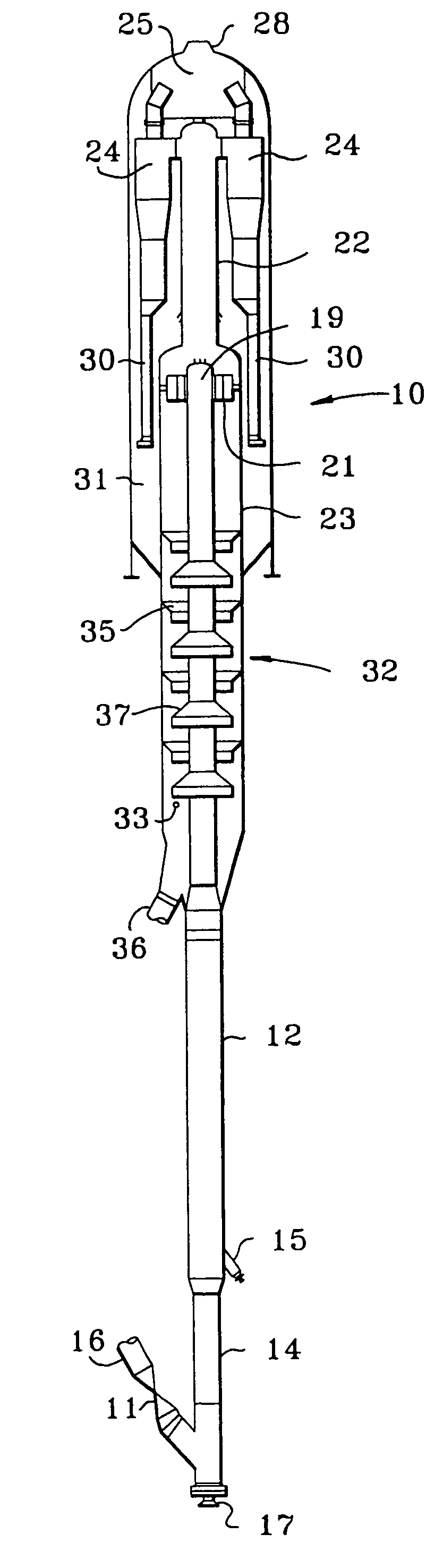
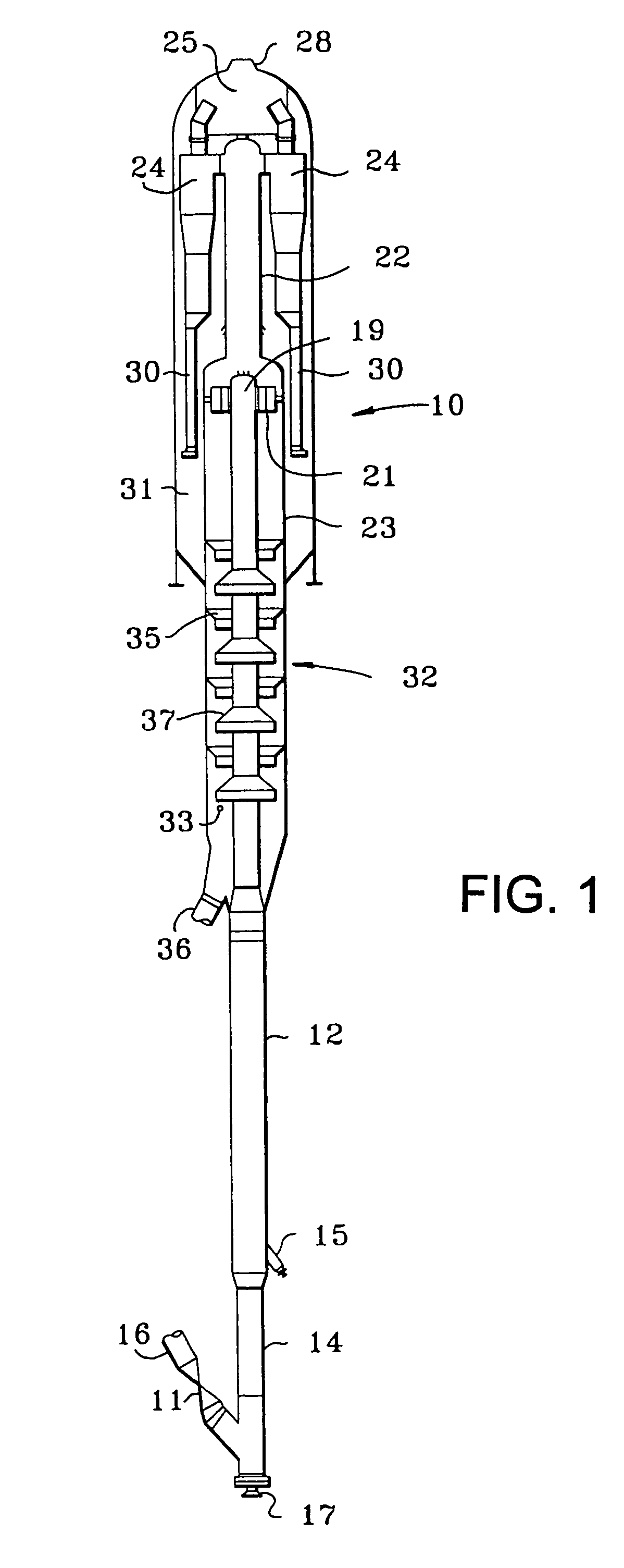
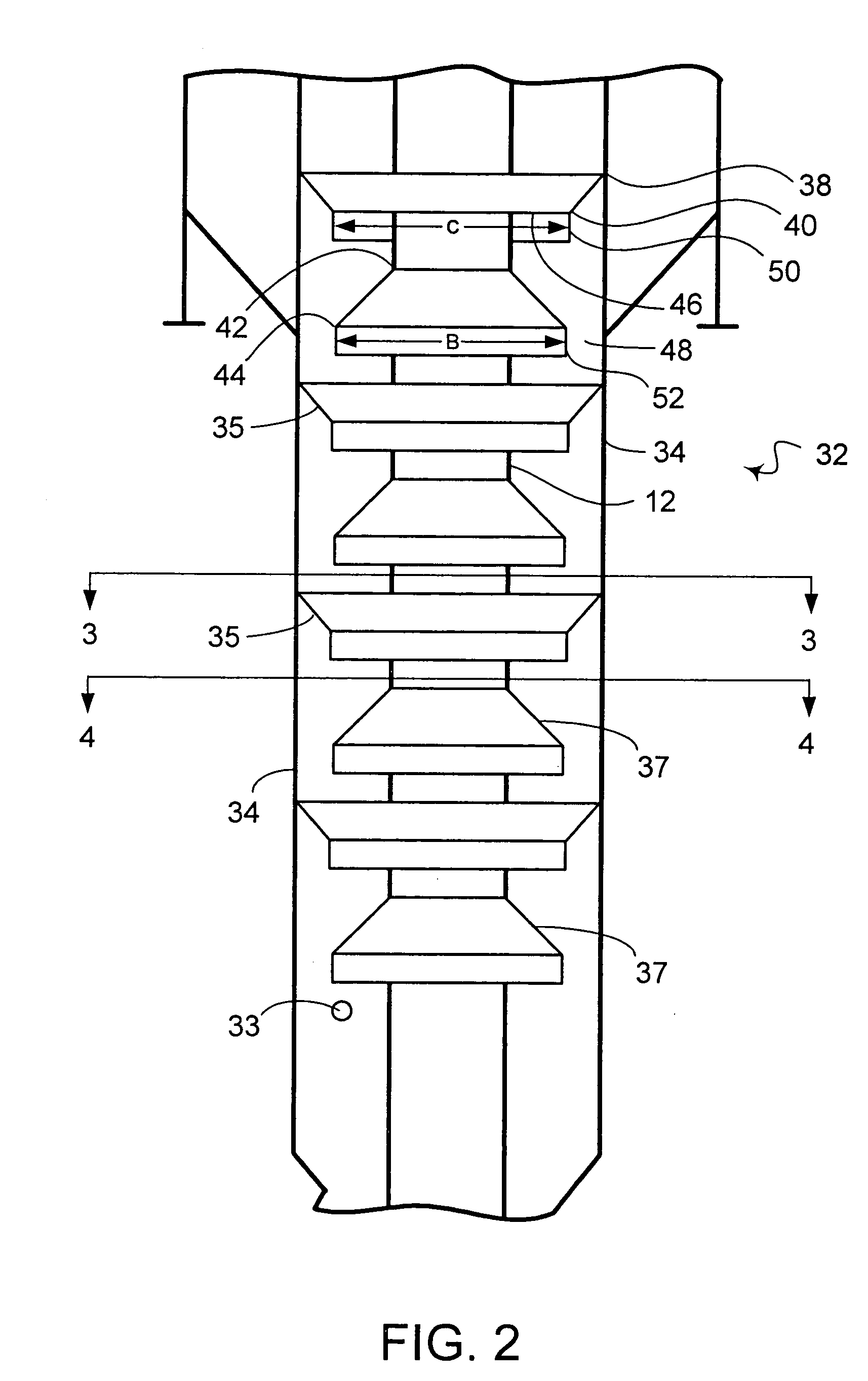
[0048]Baffles similar to the outer baffle 35 and the inner baffle 37 depicted in FIGS. 3 and 4, respectively, were designed to have the following performance when installed in a stripper section such as stripper section 32 shown in FIGS. 1 and 2. The opening diameter was designed to be 1.3 cm (0.5 inches) except for the top row of openings in each baffle in which the opening diameter was designed to be 1.0 cm (0.375 inches).

[0049]

Outer Baffle 35Row ofNumber ofRatio of Total Area ofTotal Volumetric FlowOpeningsOpeningsOpenings to BaffleRate per Row(FIG. 3)per RowSection per Row(m3 / s (ft3 / s))72600.00210.225 (7.91) 70600.00290.336 (11.86)68800.00390.349 (12.32)66120 0.00580.306 (10.79)

The ratio of total area of openings to area of baffle section in top section 60 including just row 72 is 0.0021 which is less than the same ratio of 0.0387 for bottom baffle section 62 including rows 66, 68 and 70. The total volumetric flow rate of row 72 of openings in top section 60 is 0.225 m3 / s (7.91 ...


PUM

PropertyMeasurementUnit
temperatureaaaaaaaaaa
angleaaaaaaaaaa
boiling pointsaaaaaaaaaa

Abstract

A baffle-style stripper for an FCC process comprising sloped baffles in which a greater volumetric flow rate of stripping medium permeates openings in a bottom section of the baffle than through a top section of the baffle for low catalyst flux stripping operations. When low catalyst flux is used, the catalyst runs from baffle to baffle closer to the bottom edge of the baffle. Hence, more fluidization from stripping medium is concentrated near the lower edge of the baffle. The greater fluidization at the bottom section of the baffle is accomplished by providing greater opening area per baffle area in the lower section of the baffle than in the top section of the baffle.

Description

CROSS-REFERENCE TO RELATED APPLICATION[0001]This application is a Division of application Ser. No. 09 / 990,244 filed Nov. 21, 2001, now U.S. Pat. No. 6,780,308, the contents of which are hereby incorporated by reference in its entirety.BACKGROUND OF THE INVENTION[0002]This invention relates to processes and apparatus for the fluidized contacting of catalyst with hydrocarbons. More specifically, this invention relates to processes and apparatus for stripping entrained or adsorbed hydrocarbons from catalyst particles.DESCRIPTION OF THE PRIOR ART[0003]A variety of processes contact finely divided particulate material with a hydrocarbon containing feed under conditions wherein a fluid maintains the particles in a fluidized condition to effect transport of the solid particles to different stages of the process. Catalyst cracking is a prime example of such a process that contacts hydrocarbons in a reaction zone with a catalyst composed of finely divided particulate material. The hydrocarbo...

Claims


Application Information

Patent Timeline
Patent Type & Authority Patents(United States)
IPC IPC(8): B01J8/00C10G11/18
CPCC10G11/18
Inventor HEDRICK, BRIAN W.NGUYEN, THUY KHANH T.
Owner UOP LLC
Why Eureka
Try Eureka