
Blood Pump Having A Passive Non-Contacting Bearing Suspension

a blood pump and bearing suspension technology, applied in the direction of prosthesis, liquid fuel engine, therapy, etc., can solve the problems of unresolved phenomenon, achieve sufficient deflection, improve stability, and easily measure the axial position of the rotor

Inactive Publication Date: 2008-10-23
GOLDOWSKY MICHAEL P
View PDF0 Cites 40 Cited by
  • Summary
  • Abstract
  • Description
  • Claims
  • Application Information

AI Technical Summary

Benefits of technology

[0011]Accordingly, there are three primary objects of the present invention. One is to provide a totally passive, non-contacting rotor suspension (requiring no control electronics). Another is to provide an axial thrust bearing possessing sufficient deflection and having a passive restoring stiffness independent of blood properties to absorb rotor axial forces without contact. Thirdly, is the ability to easily measure rotor axial position to obtain LVAD differential pressure.
[0013]It is also an important object of this invention to reliably and accurately sense differential pressure by incorporating a “smart thrust bearing” (one that is a transducer as well as a bearing). Differential pressure can be the basis for creating not only pulsating flow to mimic the natural heart but to provide physiologic flow control responsive to exercise level. It is yet another object to accomplish physiologic control in a safe manner by sensing and avoiding adverse suction at the pump inlet based (at least in part) on pump differential pressure.
[0015]These and other objects of the present invention are provided in a structure for a turbo blood-pump using passive non-contacting smart bearing suspension. The present invention creates a hybrid bearing, which is not a full magnetic suspension. Since the instant invention does not employ a purely magnetically suspended rotor, the rotor can be totally passive without violating Ernshaw's Law. The invention suspends the rotor radially using a mechanical hydrodynamic journal bearing; these type bearings are finding application in third generation pumps. The magnetic part of the instant suspension is only axial and a passive magnet is employed in this axis. For high quality of life for the patient, providing pulsating flow (to minimize thrombosis and to increase blood perfusion of organs) as well as physiologic flow rate control (responsive to exercise level) is highly desired. The passive axial thrust bearing stiffness of the instant magnet pairs allows tailored and substantial axial deflection of the rotor for accurate measurement (yet the bearing can absorb shock without contact). Monitoring rotor axial position by having a “smart bearing” is one that allows monitoring LVAD differential pressure on which one may, at least in part, base physiologic control. Use of differential pressure for control is claimed in the Goldowsky patent cited above. That this is a practical way to control turbo pumps is documented in a scholarly paper by Giridharan, et al, entitled Modeling and Control of a Brushless DC Axial Flow Ventricular Assist Device, ASAIO Journal volume 48, No. 3, 2002.

Problems solved by technology

This phenomenon has not yet been addressed in the design of present art turbo pumps.

Method used


Image

  • Blood Pump Having A Passive Non-Contacting Bearing Suspension
  • Blood Pump Having A Passive Non-Contacting Bearing Suspension
  • Blood Pump Having A Passive Non-Contacting Bearing Suspension

Examples


Embodiment Construction

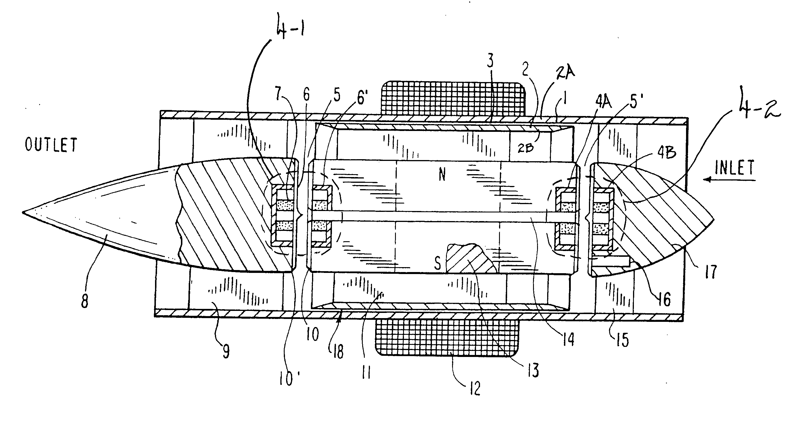
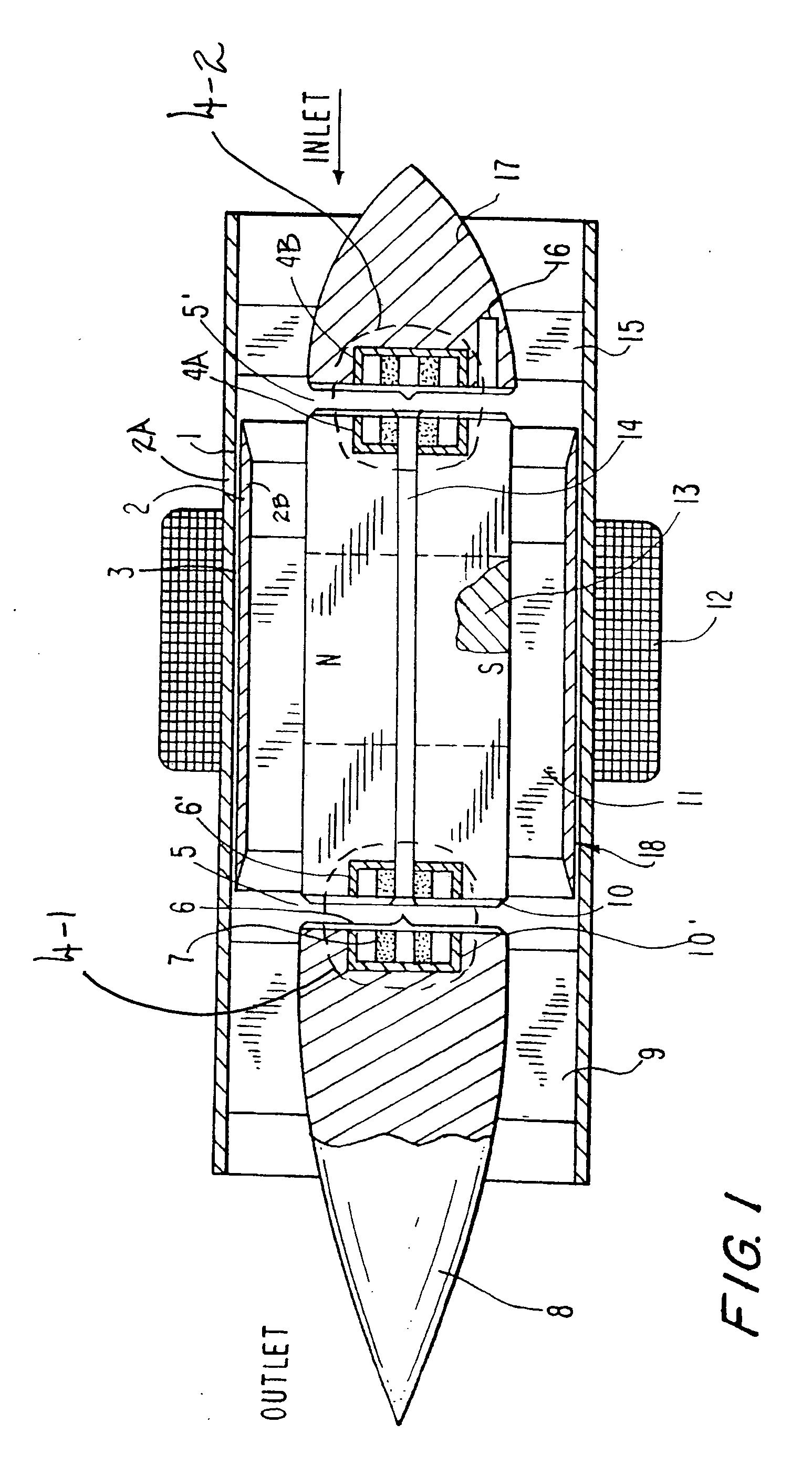
[0029]FIG. 1 is a longitudinal cross section through a preferred cylindrical axial flow turbo pump. FIG. 1 possesses limited detail, but has the essential elements of a similar axial flow pump described in FIG. 1 of Goldowsky U.S. Pat. No. 6,527,699. Only the major components of an axial flow turbo pump are shown in FIG. 1 in order to best describe the essential elements of the instant invention. An axial flow pump is illustrated and is not meant to be limiting. The same bearing suspension also applies to use in centrifugal turbo pumps. This is illustrated in the Goldowsky patent cited above.

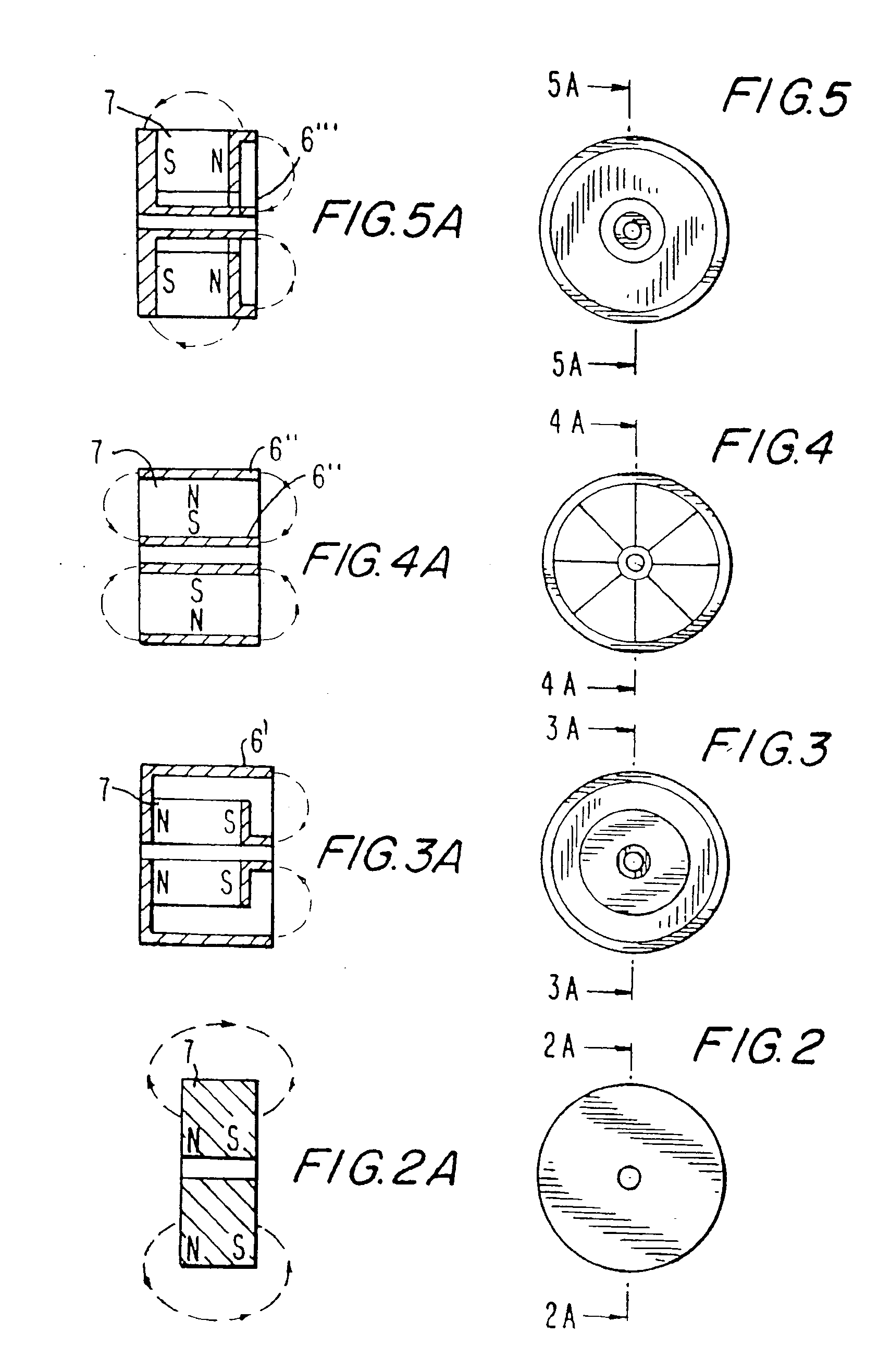
[0030]A pump rotor is generally depicted as item 18. It includes helical impeller blades 11, a radial hydrodynamic bearing, i.e., a hydrodynamic bearing 2, axial magnet thrust bearings at each end (i.e., thrust bearings 4-1 and 4-2, each of which is shown in a dashed circle), thin windows 10 and 10′, brushless motor armature magnets 13, and a blood conduit 14 used to wash out axial rotor gaps at...


PUM


Abstract

There is provided a non-contact, passively suspended blood pump that includes (a) a housing; (b) a pump rotor within the housing, wherein the pump rotor has a first end and a second end, and an axis of rotation; (c) a first axial thrust bearing across a first axial gap, between the first end and the housing, that axially suspends the first end; (d) a second axial thrust bearing across a second axial gap, between the second end and the housing, that axially suspends the second end; (e) a first radial hydrodynamic bearing that radially suspends the first end; and (f) a second radial hydrodynamic bearing that radially suspends the second end. Determining pump differential pressure by monitoring rotor axial position allows automatic physiologic control.

Description

BACKGROUND OF THE INVENTION[0001]1. Field of the Invention[0002]This invention relates to axial or centrifugal turbo blood pumps and more particularly to such blood pumps whose rotor is passively suspended, for measuring left ventricular assist devices (LVAD) differential pressure.[0003]2. Description of the Related Art[0004]First generation blood pumps utilized and still utilize flexible pumping ventricles in contact with blood. They have no blood immersed bearings and not prone to thrombosis. An advantage is their inherent pulsating flow. For one disadvantage they are too large for competitive use as LVADs (Left Ventricular Assist Devices). Newer second-generation turbo pumps have a high rpm impeller like the Jarvik 2000 and Micromed axial flow pumps. They are much smaller but have contacting bearings that suspend the rigid motor. Most second-generation pumps are the larger centrifugal type. In axial and centrifugal turbo pumps, bearing contact results in undesirable clot formatio...

Claims


Application Information

Patent Timeline
Patent Type & Authority Applications(United States)
IPC IPC(8): A61M1/10
CPCA61M1/101A61M1/1015A61M1/1017A61M60/824A61M60/82A61M60/422A61M60/148A61M60/232A61M60/178A61M60/531
Inventor GOLDOWSKY, MICHAEL P.
Owner GOLDOWSKY MICHAEL P
Learn More