Flexible Connector Interface Rib with Saw Tooth Cross Section

a flexible connector and cross section technology, applied in the field of flexible ribs, can solve the problems of difficult to provide an arresting feature, and achieve the effects of low friction resistance during insertion, high frictional resistance, and sufficient deflection

Active Publication Date: 2011-05-19
LARKIN KEVIN B
View PDF8 Cites 0 Cited by
  • Summary
  • Abstract
  • Description
  • Claims
  • Application Information

AI Technical Summary

Benefits of technology

[0004]A surrounding tubular protrusion at a connector interface features continuous circumferential ribs that extend radially outward from the outside mating face of the surrounding tubular protrusion. The continuous circumferential ribs are of a softness that provides for sufficient deflection when the tubular protrusion is inserted into a mating female cavity. As two connectors are connected, the ribs are radially compressed and provide on one hand a snug connection such that a substantially air tight interface cavity is created inside the female cavity. The flexible ribs have a saw tooth like cross section that assists on one hand in a one directional venting of air out of the interface cavity during insertion while blocking air to flow back into the interface cavity while the connector is pulled out. This creates an ambient air pressure assisted arresting effect. On the other hand, the saw tooth like cross section provides for a low friction resistance during insertion and a high frictional resistance against pull out of the connector. The flexible ribs may be monolithically fabricated together with the surrounding tubular protrusion and the remainder of the housing.

Problems solved by technology

Unfortunately, the relatively soft nature of the tubular protrusion makes it difficult to provide an arresting feature that assists in keeping the connector connected against eventual pulling forces, vibrations and such.

Method used


Image

  • Flexible Connector Interface Rib with Saw Tooth Cross Section
  • Flexible Connector Interface Rib with Saw Tooth Cross Section
  • Flexible Connector Interface Rib with Saw Tooth Cross Section

Examples


Embodiment Construction

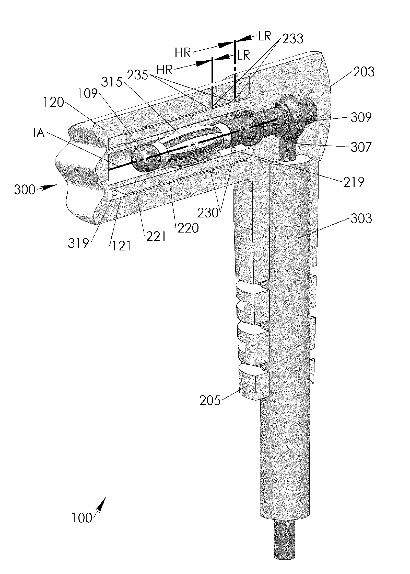
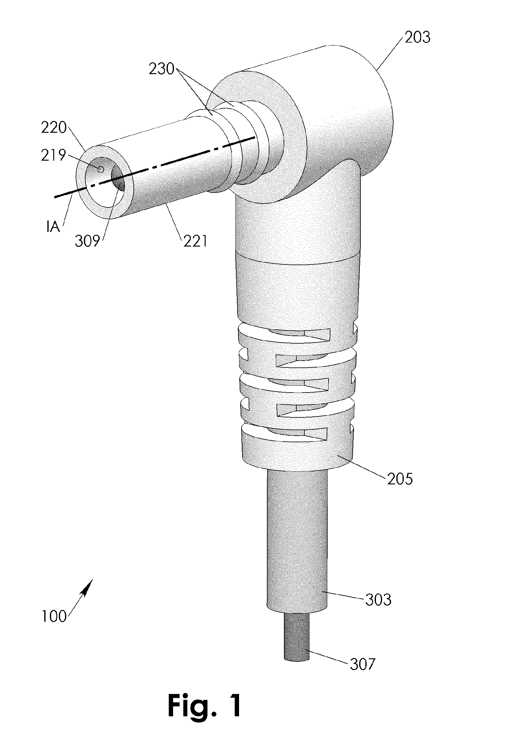
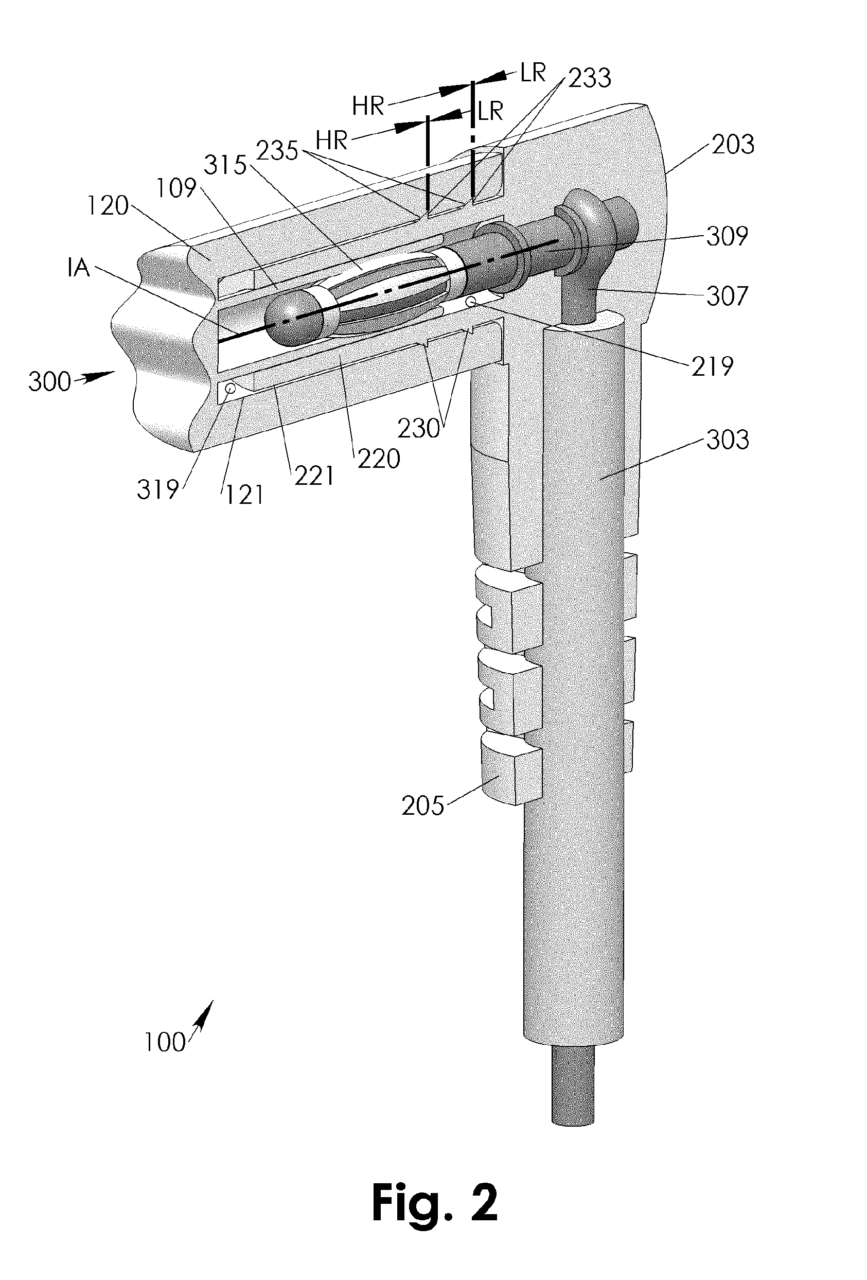
[0009]Referring to FIGS. 1-4, a connector 100 has an insertion axis IA along which it may be connector to another mating connector 300 a portion of which is depicted in FIG. 2. The connector 100 has a mating face 221 with one or more flexible ribs 230 that extend above the mating face 221 and propagate along the mating face 221 at least in a substantial angle with respect to the insertion axis IA. Preferably the flexible ribs 230 are perpendicular with respect to the insertion axis IA and circumferentially continuous on the outward mating face 221.

[0010]The flexible ribs 230 have a saw tooth cross section including a steep flank 233 and a shallow flank 235. The shallow flank 233 is in a first flank angle 235A with respect to the insertion axis IA and the steep flank 235 is in a second flank angle 233A with respect to the insertion axis IA. While the connector 100 is operationally connected, a connector interface may be defined with an opposing inward mating face 121 of the other mat...


PUM


Abstract

One or more saw tooth shaped flexible ribs in between a connector interface provide asymmetric sliding resistance and a one sided sealing effect. The asymmetric sliding resistance provides for low frictional engaging resistance and for a high disengaging resistance of the connector interface. The one sided sealing effect provides in conjunction with an interface cavity for back flow resistance into the cavity during disengagement movement in the interface and for a vacuum effect that assists in opposing the disengagement movement. The flexible ribs may be monolithically fabricated together with the entire housing of the respective connector.

Description

CONTINUATION[0001]The present application is a Continuation of and from US patent application of the same Title and Inventor, application Ser. No. 12 / 240,177, filed Sep. 29, 2008.FIELD OF INVENTION[0002]The present invention relates to flexible ribs in the connector interface of connectors that provide asymmetric friction resistance and one directional sealing.BACKGROUND OF INVENTION[0003]Signal transmitting connectors such as peripheral electrical connectors commonly employ an overall housing that is monolithically encompassing the connector's terminal(s) while providing a strain relief at the same time. Such overall housing is preferably made of plastic that is sufficiently soft to provide sufficient impact resistance and flexural elasticity for the integrated strain relief as is well known in the art. In the prior art, the electric terminal(s) have been also surrounded by a surrounding tubular protrusion that is intended to fit snugly into a mating female cavity of another connec...

Claims


Application Information

Patent Timeline
Patent Type & Authority Applications(United States)
IPC IPC(8): H01R13/52
CPCH01R13/567H01R2101/00H01R43/24H01R24/28
Inventor LARKIN, KEVIN B.
Owner LARKIN KEVIN B
Why Eureka
Try Eureka