Remote radio data communication system with data rate switching

a radio data communication and data rate technology, applied in the field of radio data communication system improvement, can solve the problems of reducing the effective communication range, excessive digital noise generation in and around the rf terminal, etc., and achieve the effect of efficient transmission energy conservation and effective operation

Inactive Publication Date: 2010-02-18
AVAGO TECH WIRELESS IP SINGAPORE PTE
View PDF8 Cites 45 Cited by
  • Summary
  • Abstract
  • Description
  • Claims
  • Application Information

AI Technical Summary

Benefits of technology

[0048]Accordingly, an important object of the present invention is to provide a dormant polling protocol that effectively operates during periods of both heavily and lightly loaded communication.
[0049]A further object of the invention is to provide a radio data communication system utilizing a dormant polling protocol to effectively operate during periods of both heavily and lightly loaded communication.
[0050]Another object of the invention is to provide a radio data communication system utilizing a dormant polling protocol to efficiently conserve transmission energy.

Problems solved by technology

However, the high clock rates used for decoding also may cause the generation of an excessive amount of digital noise in and around the rf terminals.
This noise can get into the rf terminal and interfere with communication, resulting in a reduction in the effective communication range.

Method used


Image

  • Remote radio data communication system with data rate switching
  • Remote radio data communication system with data rate switching
  • Remote radio data communication system with data rate switching

Examples


Embodiment Construction

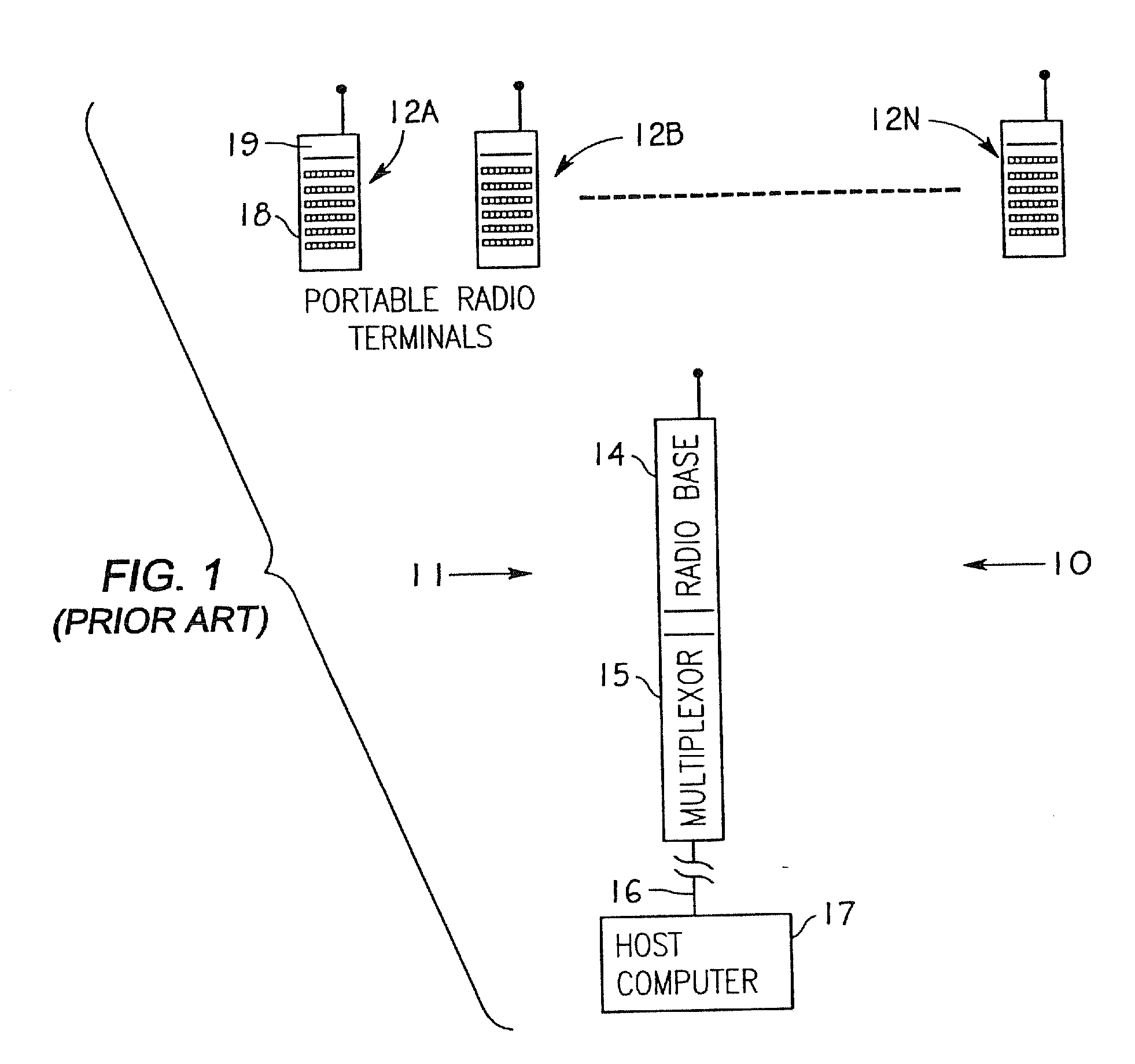
[0100]FIG. 1 shows an existing radio frequency data transmission system 10 wherein a base station transceiver means 11 has a number of mobile transceiver units such as 12A, 12B, . . . , 12N in radio communication therewith.

[0101]By way of example, the base station may be comprised of a radio base unit 14 such as the model RB3021 of Norand Corporation, Cedar Rapids, Iowa, which forms part of a product family known as the RT3210 system. In this case, the radio base 14 may receive data from the respective mobile RF terminals, e.g. of type RT3210 or RT1210, and transmit the received data via a multiplexor 15 and a communications link 16 (e.g. utilizing an RS-232 format) to a host computer 17.

[0102]The data capture terminals 12A, 12B, . . . , 12N may each be provided with a keyboard such as 18, a display as at 19, and a bar code scanning capability, e.g., via an instant bar code reader such as shown in U.S. Pat. No. 4,766,300 issued Aug. 23, 1988, and known commercially as the 20 / 20 High...


PUM


Abstract

In an exemplary communication system, a multiplicity of mobile terminals are to share a communication link with a host processor communicating through base transceivers. The mobile terminals evaluate communication signals being transmitted to one or more of the mobile transceivers and according to the evaluation of such signals, each mobile terminal independently selects a relatively high data rate or a lower more conservative data rate for communication with the host processor. The mobile terminal enters a dormant state after a fixed period elapses during which the mobile unit is not engaged in communication with the base station. Periodically, the mobile terminal reenters active state in receive mode for a brief interval and if no polling signal or other message directed to the mobile terminal is present, the mobile terminal returns to dormant state. When a signal is directed to the mobile terminal, the mobile terminal remains in active receive mode until a fixed period after a communication session is completed and then returns to dormant/active cycling. A base station utilizing a dormant polling protocol transmits polling sequences to a plurality of remote transceivers during periods of heavy loading. During periods of low loading, the base station stops polling and enters into a dormant state, listening for communication request from the remote transceivers. Upon receiving such a request, the base station immediately responds by servicing the requesting remote transceiver. In this way, the base station provides optimized utilization of the communication channel during periods of heavy and light loading conditions.

Description

CROSS-REFERENCE TO RELATED APPLICATION[0001]The present application is a consolidation of application Ser. Nos. 09 / 934,457 and 09 / 799,340, and is in part a continuation of application Ser. No. 09 / 934,457 filed Aug. 21, 2001 and in part a continuation of application Ser. No. 09 / 799,340 filed Mar. 5, 2001, without the introduction of any further matter. Said application Ser. No. 09 / 934,457 is a continuation of application Ser. No. 08 / 551,442 filed Nov. 1, 1995, which is a continuation of application Ser. No. 07 / 910,865 filed Jul. 6, 1992, now abandoned; said application Ser. No. 07 / 910,865 is a continuation-in-part of application Ser. No. 07 / 864,300 filed Apr. 6, 1992, now abandoned; and a continuation-in-part of application Ser. No. 07 / 980,947 filed May 26, 1992, now abandoned.[0002]Said application Ser. No. 07 / 910,865 is a continuation-in-part of application Ser. No. 07 / 883,854, filed May 13, 1992 now abandoned (Attorney Docket Nos. 92 P 367; DN36500ZA), which is a continuation-in-p...

Claims


Application Information

Patent Timeline
Patent Type & Authority Applications(United States)
IPC IPC(8): H04B1/40
CPCH04W74/06
Inventor MAHANY, RONALD L.LUCKEN, PAMELA
Owner AVAGO TECH WIRELESS IP SINGAPORE PTE
Why Eureka
Try Eureka