Method for lining an existing pipe and collar for protecting a lining material

a technology of lining material and pipe, which is applied in the direction of flexible pipes, pipes, pipe elements, etc., can solve the problems of not being able to accurately measure the intersection angle of the main pipe and the branch pipe, and not being able to plug up,

Inactive Publication Date: 2006-10-17
SHONAN GOSEI JUSHI SEISAKUSHO KK
View PDF4 Cites 9 Cited by
  • Summary
  • Abstract
  • Description
  • Claims
  • Application Information

AI Technical Summary

Benefits of technology

[0018]According to the invention, the flange can be made into a shape corresponding to the surface surrounding the pipe opening of the existing pipe, and the angle of the flange surface relative to the axial direction of the inserted lining material can be made to match the angle of intersection of the existing pipe and the flange mounting surface. This assures that the flange can completely seal the gap between the inner circumference of the existing pipe and the outer circumference of the lining material at the circumferential edge part of the pipe opening of the existing pipe and the infiltration of external ground water, rainwater, and the like can be reliably prevented.

Problems solved by technology

If, after lining the branch pipe, the main pipe is lined including the portion that intersects with the branch pipe, then the lining material of the main pipe unfortunately plugs up the pipe opening of the branch pipe at the intersecting portion.
Nevertheless, it may not necessarily be possible to accurately measure the angle of intersection of the main pipe with the branch pipe, and the shape of the flange fixing surface by the previously performed pre-examination.
In particular, accurate measurement is problematic in cases where a person cannot enter the main pipe and perform a direct measurement because the diameter of the main pipe is small, and the measurement must be taken indirectly by a video camera vehicle, and the like.
If, therefore, the measurement error is large, then the flange of the lining material can no longer be tightly sealed and fixed to the entire surface of the flange fixing surface.
In this case, the gap between the inner circumference of the branch pipe and the outer circumference of the branch pipe liner at the circumferential edge part of the pipe opening of the branch pipe can no longer be completely sealed by the flange, and the infiltration of external ground water, rainwater, and the like, can no longer be prevented.
If, therefore, the measurement error is large, then the flange of the lining material can no longer be tightly sealed to the entire surface of the flange fixing surface.

Method used


Image

  • Method for lining an existing pipe and collar for protecting a lining material
  • Method for lining an existing pipe and collar for protecting a lining material
  • Method for lining an existing pipe and collar for protecting a lining material

Examples


Embodiment Construction

[0027]The present invention will be described based on preferred embodiments, referring to the attached drawings.

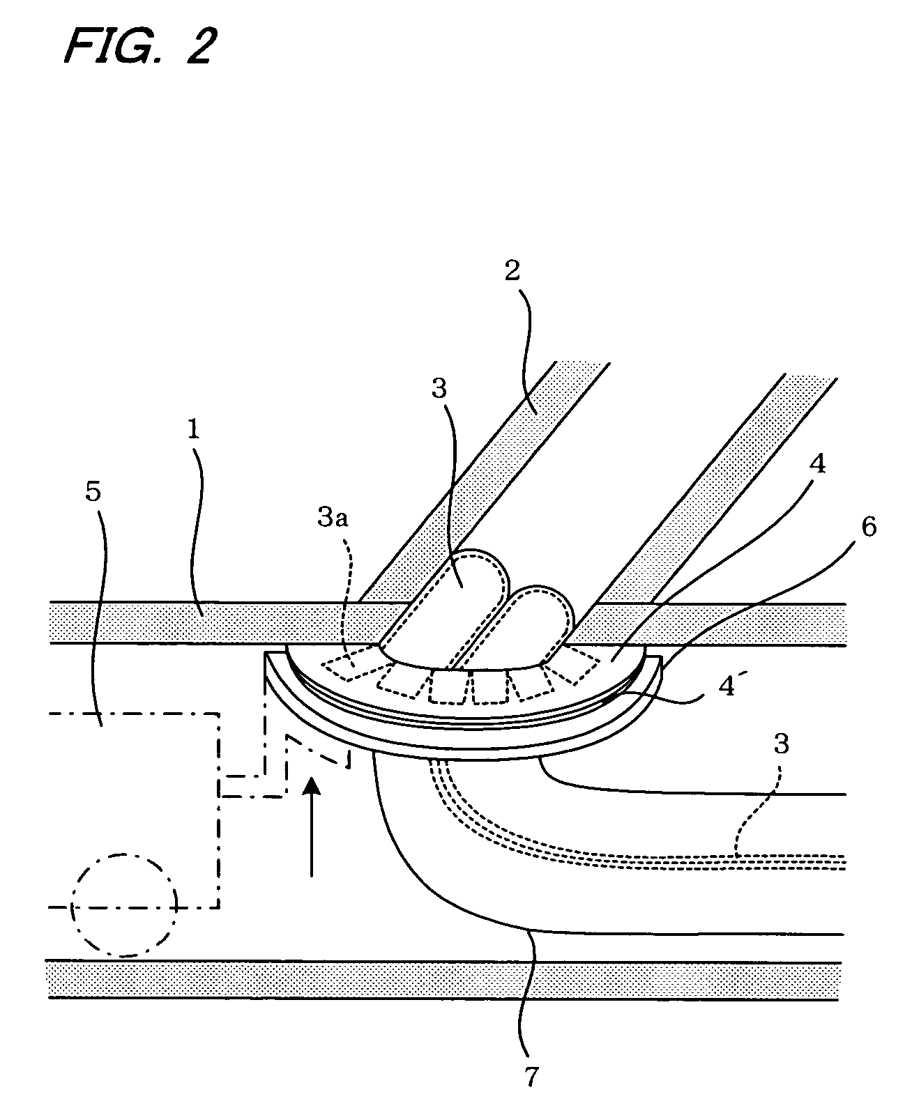
[0028]According to an embodiment shown in FIG. 2 and FIG. 3, an inner circumferential surface of a branch pipe 2 is lined from the pipe opening of the branch pipe 2 that intersects with a main pipe 1 such as a sewer pipe at an angle of approximately 45 degrees. The main pipe 1 and the branch pipe 2 are both circular pipes. In the pre-examination, measurements are previously performed with respect to the angle of intersection of the main pipe 1 with the branch pipe 2, more precisely the angle of the branch pipe 2 in an axial direction relative to the flange fixing surface (the axial direction of the main pipe 1) and with respect to the shape (curvature, and the like) of the flange fixing surface and the shape of the pipe opening, and the like.

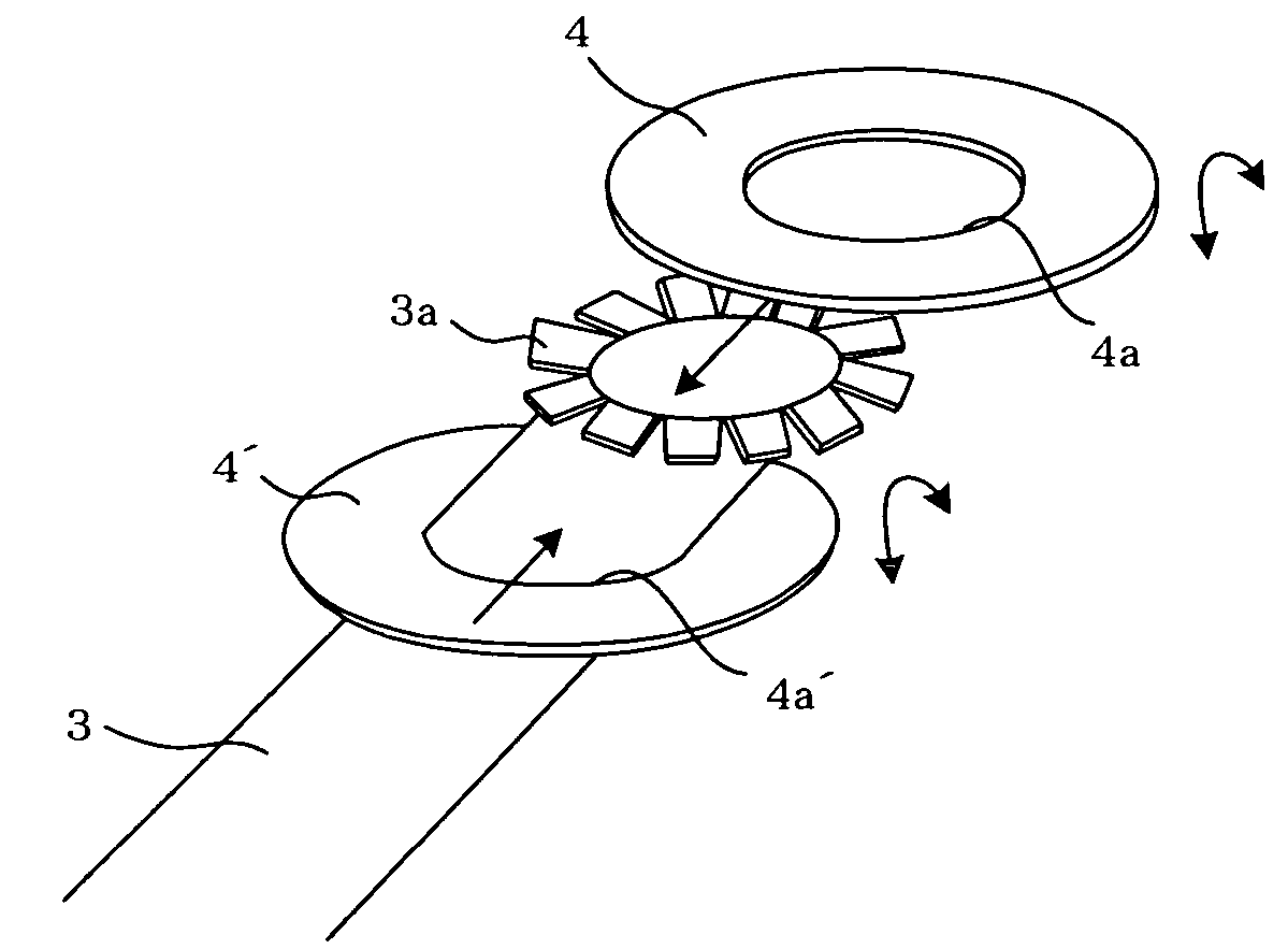
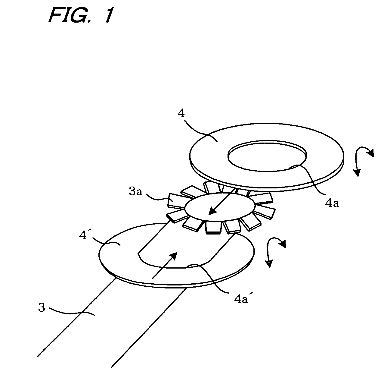
[0029]FIG. 1 shows the appearance of a liner or lining material 3 used in the present embodiment, and two flanges 4, 4′ joined to on...


PUM


Abstract

A method for lining an existing pipe uses a tubular lining material comprising a flexible resin absorber impregnated therein with a liquid setting resin. One end part of the lining material is radially spread to form cut pieces. The cut pieces of the lining material are laid on a flange comprising a flexible resin absorber impregnated with a liquid setting resin. The flange and the cut pieces of the lining material are brought into pressure contact with a surface surrounding a pipe opening of the existing pipe before a step of evertedly inserting the lining material into the existing pipe. The liquid setting resin in the flange and the cut pieces of the lining material is cured to adhesively fix the flange and the cut pieces of the lining material to the surface surrounding the pipe opening of the existing pipe.

Description

BACKGROUND OF THE INVENTION[0001]1. Field of the Invention[0002]The present invention relates to a method for lining an inner circumferential surface of an existing pipe such as a sewer pipe with a lining material, and to a lining material collar for protecting one end part of the lining material.[0003]2. Description of the Prior Art[0004]In a conventional method of lining an existing pipe, as disclosed in Japanese Patent Publication No. 1980-43890, a lining material comprising a tubular (bag shaped) flexible resin absorber impregnated with a liquid setting resin is inserted into the existing pipe with the liquid setting resin in an uncured form. The lining material is then brought into pressure contact with an inner circumferential surface of the existing pipe by air pressure, water pressure, and the like, and cured by heating and hardening the setting material so that it becomes tubular with a shape the same as the inner circumferential surface of the existing pipe.[0005]In such a...

Claims


Application Information

Patent Timeline
Patent Type & Authority Patents(United States)
IPC IPC(8): F16L55/16
CPCF16L55/179F16L55/1651
Inventor KANETA, KOJIKAMIYAMA, TAKAOFUJII, KENJIHASEGAWA, TAKESHI
Owner SHONAN GOSEI JUSHI SEISAKUSHO KK
Why Eureka
Try Eureka