Air passage switching device and vehicle air conditioner

a switching device and air passage technology, applied in vehicle maintenance, vehicle cleaning, wing accessories, etc., can solve problems such as inability to completely seal

Inactive Publication Date: 2007-10-23
DENSO CORP
View PDF24 Cites 7 Cited by
  • Summary
  • Abstract
  • Description
  • Claims
  • Application Information

AI Technical Summary

Benefits of technology

[0008]In view of the above-described problems, it is an object of the present invention to provide an air passage switching device which can completely seal a sealing portion when one of first and second opening portions is closed. The air passage switching device can be suitably used for a vehicle air conditioner.
[0012]Furthermore, the link portion can be provided at a first end position of the slide door, close to the second opening portion when the slide door fully closes the first opening portion. In this case, a guide pin is provided at a second end portion far from the second opening portion when the slide door fully closes the first opening portion, and only the guide pin is engaged with the guide member to be slidable relative to the guide member. Therefore, the sealing structure of the air passage switching device can be readily formed with a simple structure.
[0013]The first opening portion and the second opening portion can be arranged on surfaces bent at the partition portion. In this case, the partition portion is bent to correspond to the bent surfaces, the guide member is arranged only in a range corresponding to the first opening portion in the sliding direction, and the first end portion of the slide door is bent to correspond to the bent partition portion. Therefore, the air passage switching device can be easily mounted in a limited small space.
[0014]Further, the guide member can be provided, such that a press-contacting force of the first and second seal portions of the slide door to the outer peripheral portion of the first and second opening portions and the partition portion is larger when the slide door fully closes one of the first and second opening portions, as compared with a case where both the first and second opening portions are opened by the slide door. Therefore, the sealing performance of the slide door can be effectively improved while slide resistance and slide noise can be restricted.

Problems solved by technology

However, in both the slide doors, when one passage opening portion is closed by the slide door 12A or 12B, a sealing may be not completely performed.

Method used


Image

  • Air passage switching device and vehicle air conditioner
  • Air passage switching device and vehicle air conditioner
  • Air passage switching device and vehicle air conditioner

Examples


first embodiment

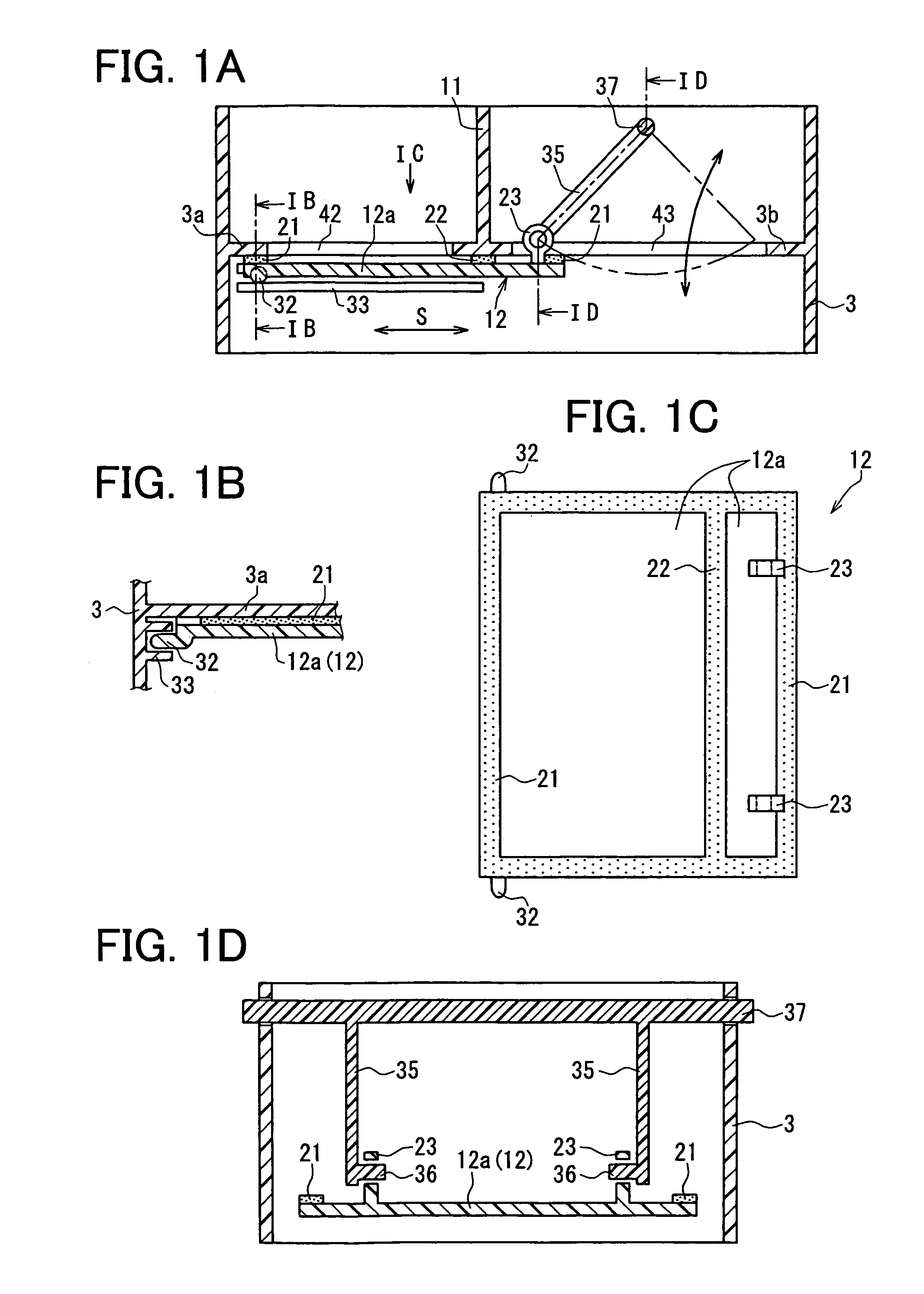
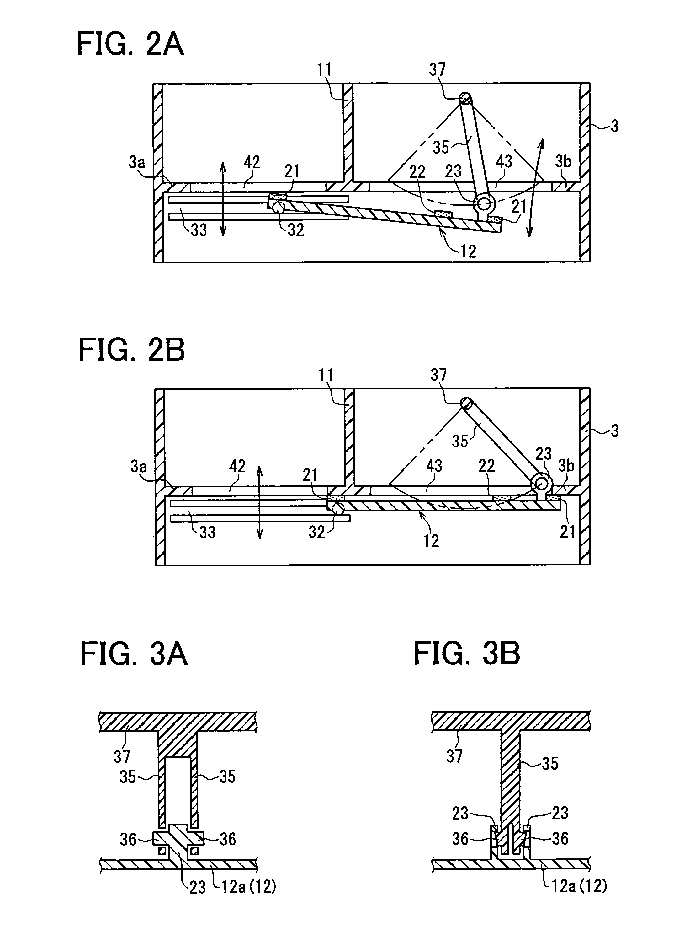
[0029]FIG. 1A is a schematic sectional view showing an air passage switching device having first and second passage opening portions 42, 43 when the first passage opening portion 42 is closed according to the first embodiment. FIG. 1B is a cross-sectional view taken along the line IB-IB in FIG. 1A, FIG. 1C is a view when being viewed from the arrow IC in FIG. 1A, and FIG. 1D is a cross-sectional view taken along the line ID-ID in FIG. 1A.

[0030]A case 3 made of resin is provided to form an air passage including the first and second passage opening portions 42, 43. The first and second passage opening portions 42, 43 are formed in the case 3 adjacent to each other, and are partitioned from each other by a partition portion 11. The partition portion 11 can be arranged in the case 3 to partition the air passage into a first passage communicating with the first passage opening portion 42 and a second passage communicating with the second passage opening portion 43.

[0031]A slide door 12 i...

second embodiment

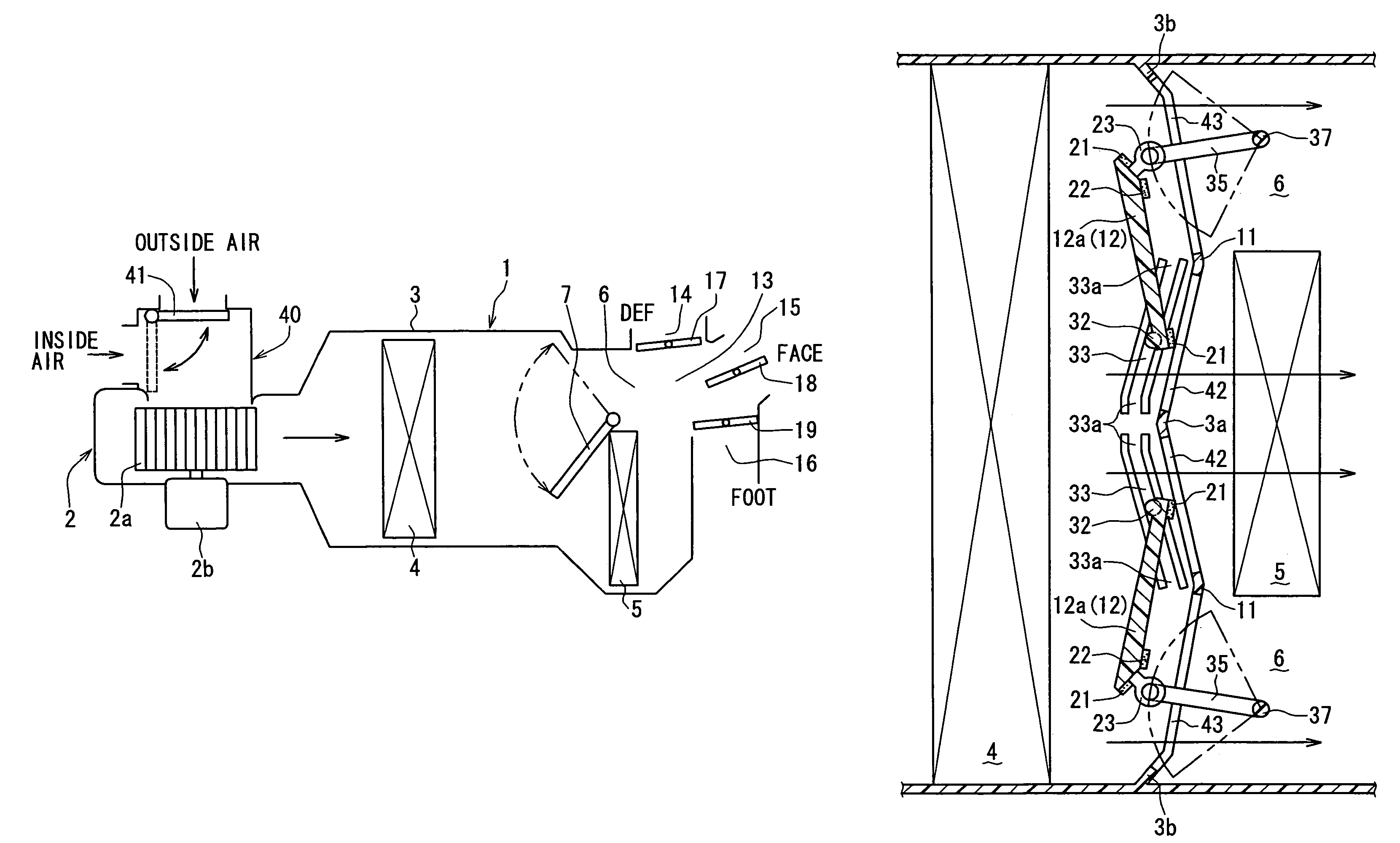
[0043]FIG. 4 is a schematic diagram showing a vehicle air conditioner having a blower unit 2 and an interior air conditioning unit 1. The interior air conditioning unit 1 can be mounted inside a dashboard on a front portion in a passenger compartment. In this embodiment, an air passage switching device is suitably used for the air conditioner.

[0044]The interior air conditioning unit 1 includes a case 3 for defining an air passage through which air flows into the passenger compartment. An evaporator 4 is disposed in the case for cooling air blown from the blower unit 2. The blower unit 2 for blowing air into the passenger compartment through the air passage is disposed upstream from the evaporator 4 in an air flow direction. The blower unit 2 is disposed in the case 3, and includes a centrifugal blower fan 2a and a driving motor 2b for driving the centrifugal blower fan 2a. Furthermore, an inside / outside air switching box 40 is located at a suction side of the blower fan 2a. An insid...

third embodiment

[0059]The third embodiment of the present invention will be now described with reference to FIGS. 6A and 6B. In the third embodiment, an air passage switching device of the present invention is typically used for an air mixing portion having an air mixing door for a vehicle air conditioner. That is, a sliding door 12 of the third embodiment is used to have the functions of the air mixing door 7 in FIG. 4. FIG. 6A shows a part of an air conditioning unit in a maximum cold state, and FIG. 6B shows a part of the air conditioning unit in a maximum hot state.

[0060]As shown in FIGS. 6A and 6B, the air conditioning unit includes a case 3 for defining an air passage, an evaporator 4 for cooling air blown from a blower unit, and a heater core 5 for heating air from the evaporator 4. The heater core 5 is located to form a cool air bypass passage through which air bypasses the heater core 5. The slide door 12 is used as an air mixing door, and is arranged to open and close an air passage of th...


PUM


Abstract

An air passage switching device includes a slide door slidable along first and second opening portions partitioned by a partition portion, a guide member for guiding the slide door, and a link mechanism for slidably moving the slide door along the guide member. The link mechanism includes a rotation shaft rotatably supported in a case, a link portion provided at one end portion of the slide door, and a link lever connected to the rotation shaft and the link portion. The link portion is rotatable around the rotation shaft only within a range of the second opening portion in a sliding direction, among the first and second opening portions. Furthermore, the slide door can be provided with a first seal portion for sealing a clearance with outer peripheral portions of the first and second opening portions, and a second seal portion for sealing a clearance with the partition portion.

Description

CROSS REFERENCE TO RELATED APPLICATION[0001]This application is based on Japanese Patent Application No. 2004-364994 filed on Dec. 16, 2004, the contents of which are incorporated herein by reference in its entirety.FIELD OF THE INVENTION[0002]The present invention relates to an air passage switching device and a vehicle air conditioner using the same. More particularly, the present invention relates to an air passage switching device in which a slide door having a plate shape is slid by a rotation of a link lever to switch an air passage.BACKGROUND OF THE INVENTION[0003]An air conditioner having a slide door is described in JP-A-8-290714 (corresponding to U.S. Pat. No. 5,701,949) and JP-A-11-20453, for example. FIG. 8 is a perspective view showing a slide door 12A in JP-A-8-290714, and FIG. 9 is a perspective view showing a slide door 12B in JP-A-11-20453. However, in both the slide doors, when one passage opening portion is closed by the slide door 12A or 12B, a sealing may be not...

Claims


Application Information

Patent Timeline
Patent Type & Authority Patents(United States)
IPC IPC(8): B60H1/26
CPCB60H1/00692
Inventor YOSHIDA, TAKAHIROYAMAMOTO, TAKASHI
Owner DENSO CORP
Why Eureka
Try Eureka