Method for Sealing a Region of Open Hole Gravel Pack

a technology for open-hole gravel and sealing, which is applied in the direction of drilling pipes, drilling casings, borehole/well accessories, etc., can solve the problem of multiple drips/lumps of alloy on the screen rather than a complete seal

Active Publication Date: 2020-02-20
CORETRAX AMERICAS LTD
View PDF0 Cites 8 Cited by
  • Summary
  • Abstract
  • Description
  • Claims
  • Application Information

AI Technical Summary

Benefits of technology

[0006]The method for sealing a region of OHGP includes the following steps: a) deploying of the sealing patch comprising tubulars with two anchor / seals and two LMT alloy elements and the expansion tool in the desired location in the well; b) operating the expansion tool to radially expand the anchor / seals in interference contact with the sand-screen; c) heating the LMT elements so that they melt and flow through the sand-screen and proppant sand in radial direction; and allowing LMT alloys to cool and form the seals.
[0007]The anchor / seals serve two purposes. First, they provide a hanging capacity to support the tubulars in the well. Second, they provide a “bridge” preventing the molten alloy from freely flowing through the annulus between the tubulars and sand screen which leads to the creation of multiple drips / lumps of alloy on the screen rather than a complete seal. Thus, the anchor / seals by preventing free flow along the screen and focusing the molten alloy at the anchor / seals allow the molten alloy to penetrate through the sand-screen and the surrounding proppant creating a complete seal.

Problems solved by technology

Second, they provide a “bridge” preventing the molten alloy from freely flowing through the annulus between the tubulars and sand screen which leads to the creation of multiple drips / lumps of alloy on the screen rather than a complete seal.

Method used


Image

  • Method for Sealing a Region of Open Hole Gravel Pack
  • Method for Sealing a Region of Open Hole Gravel Pack
  • Method for Sealing a Region of Open Hole Gravel Pack

Examples


Embodiment Construction

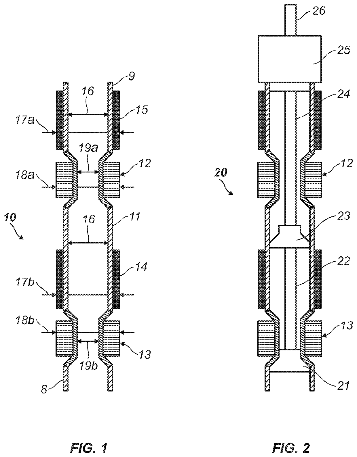
[0016]FIG. 1 shows a preferred embodiment of the sand-screen patch 10 of the present invention. The sand-screen patch 10 comprises a first tubular 9 attached to an anchor / seal 12, a second tubular 11 connected between anchor / seal 12 and a second anchor / seal 13, and optionally a third tubular 8 connected to a lower portion of anchor / seal 13. Two Low Melting Temperature (LMT) alloy elements 14 and 15 are positioned around the outer surfaces the tubular 11 and 9 respectively above the anchor / sealing elements. The terms “above” or “below” are referred to the directions to the top of the well or towards the bottom of the well correspondingly.

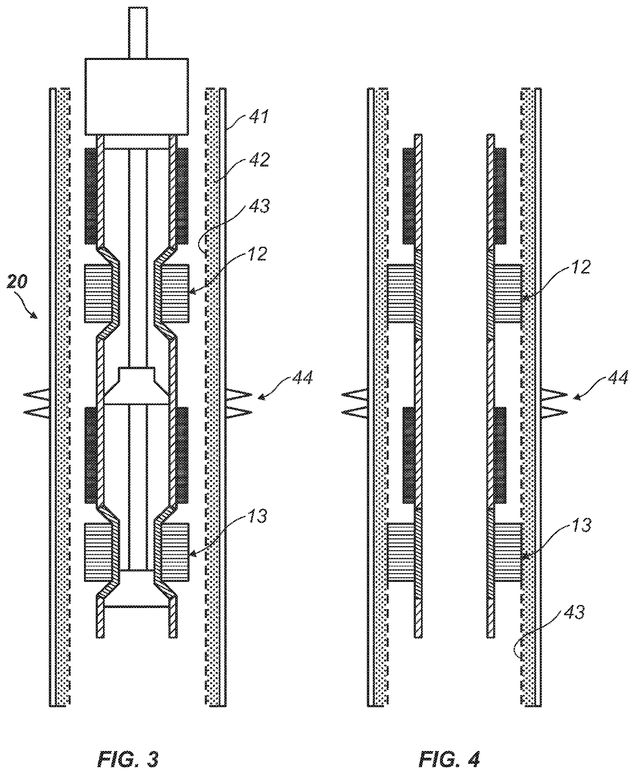
[0017]FIG. 2 shows an exemplary system 20 for sealing a region of OHGP comprising the patch 10 with the expansion tool comprising the thruster 25, two expansion devices 21 and 23, and conduit 26. The thruster 25 may be a hydraulically operated device or an explosive device providing that it may generate force necessary for expansion of the anchor / sea...


PUM

PropertyMeasurementUnit
melting pointaaaaaaaaaa
internal diametersaaaaaaaaaa
internal diameteraaaaaaaaaa

Abstract

A system for sealing a region of open hole gravel pack comprising a sealing patch and an installation tool is described. The sealing patch includes a tubular assembly including two expandable anchor/seals and two low melting temperature alloy elements positioned on outside surface of the tubular assembly above the anchor/seals. The system is deployed in desirable location in the well and the tool is operated to set anchor/seals in interference contact with sand-screen. Then the alloy elements are melted to seal the patch. The anchor/seals serve two purposes: they provide a hanging capacity to support the patch in the well and create a “bridge” preventing the molten alloy from freely flowing through the annulus between the tubular assembly and sand screen and focusing the molten alloy at the anchor/seals to flow in radial direction penetrating through the sand-screen and the surrounding proppant sand creating a complete seal.

Description

CROSS-REFERENCE TO RELATED APPLICATIONS[0001]This application claims the benefit of U.S. Provisional Application No. 62719808 filed on Aug. 20, 2018, the entire contents of which is incorporated herein by reference thereto.BACKGROUND OF THE INVENTIONField of the Invention[0002]The present invention relates to method and apparatus for sealing selected regions in open hole gravel packs in oil and gas wells.Background of the Invention[0003]Open hole completions and in particular Open Hole Gravel Packs (OHGP) may provide an effective way of oil or gas production from several different production zones. OHGPs comprise sand-screens within the annulus between the sand-screen and an open hole packed with the proppant / sand which allows flow of the oil or gas both through the annulus and sand-screen. However, over time, the production quality of particular zones diminishes due to a reduction in the percentage of desirable product and may result in overflow of water.[0004]In such cases the rem...

Claims


Application Information

Patent Timeline
Patent Type & Authority Applications(United States)
IPC IPC(8): E21B33/12E21B43/08
CPCE21B33/12E21B33/1204E21B43/08E21B15/003E21B15/02E21B19/02E21B19/15E21B19/165
Inventor BENZIE, SCOTT A.CACCIALUPPI, ALESSANDRO
Owner CORETRAX AMERICAS LTD
Why Eureka
Try Eureka