Flow stop insert apparatus and methods

a technology of flow stop and insert, which is applied in the direction of process and machine control, instruments, other domestic objects, etc., can solve the problems of difficult manufacturing or assembly, serious harm to patients, and difficult to assemble designs

Inactive Publication Date: 2014-10-30
SMITHS MEDICAL ASD INC
View PDF9 Cites 7 Cited by
  • Summary
  • Abstract
  • Description
  • Claims
  • Application Information

AI Technical Summary

Benefits of technology

[0010]Another embodiment of the present invention is directed to a cassette reservoir attachment of an infusion pump. The cassette reservoir attachment includes a reservoir housing for enclosing a quantity of fluid, an infusion tube to supply the fluid from the reservoir housing and a pressure plate. The pressure plate includes a tubing support surface for supporting a section of the infusion tube extending from the reservoir housing as well as a plurality of retention and guide features formed in the tubing support surface. The cassette reservoir attachment also includes a free flow protection device that prevents free-flow of fluid in the tube. The free flow protection device includes an attachable occlusion arch with snaps, that attach to retention and guide features, and an attachable flow stop arm, operatively coupled to the retention and guide features, for movement adjacent the attachable occlusion arch to selectively occlude an infusion tube passing through the occlusion arch.

Problems solved by technology

Free-flow may cause serious harm to a patient due to overmedication.
Although many of the free-flow prevention designs are somewhat effective, many designs suffer from arrangements that are difficult to manufacture or assemble.
For example, many current pressure plate arrangements for delivery tube placement contain features which pose hard to assemble designs.
Further, the components and operation of past pressure plate designs are believed to be less than optimal and leave considerable room for improvement.

Method used


Image

  • Flow stop insert apparatus and methods
  • Flow stop insert apparatus and methods
  • Flow stop insert apparatus and methods

Examples


Embodiment Construction

[0026]The invention may be embodied in other specific forms without departing from the essential attributes thereof, therefore, the illustrated embodiments should be considered in all respects as illustrative and not restrictive.

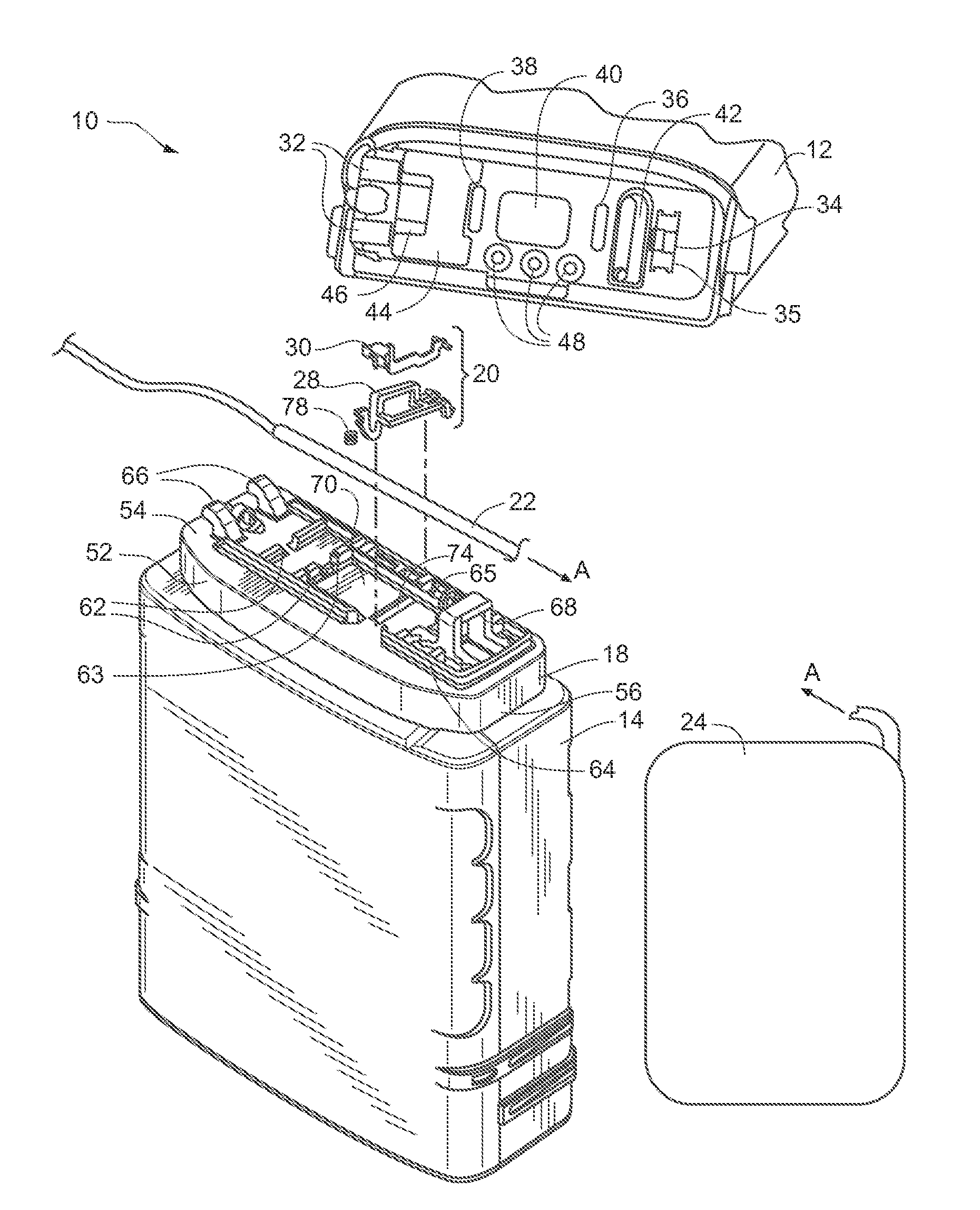
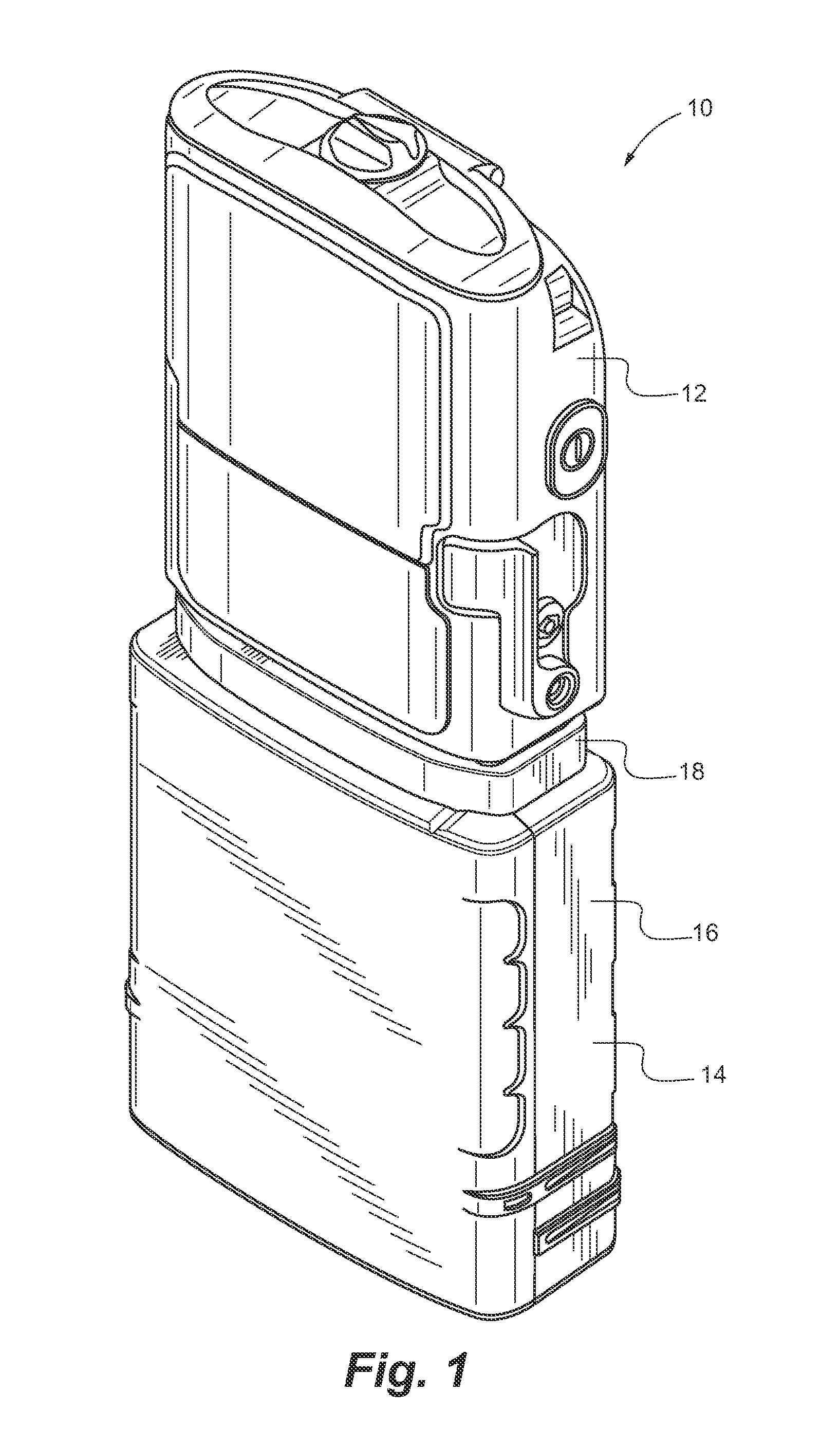
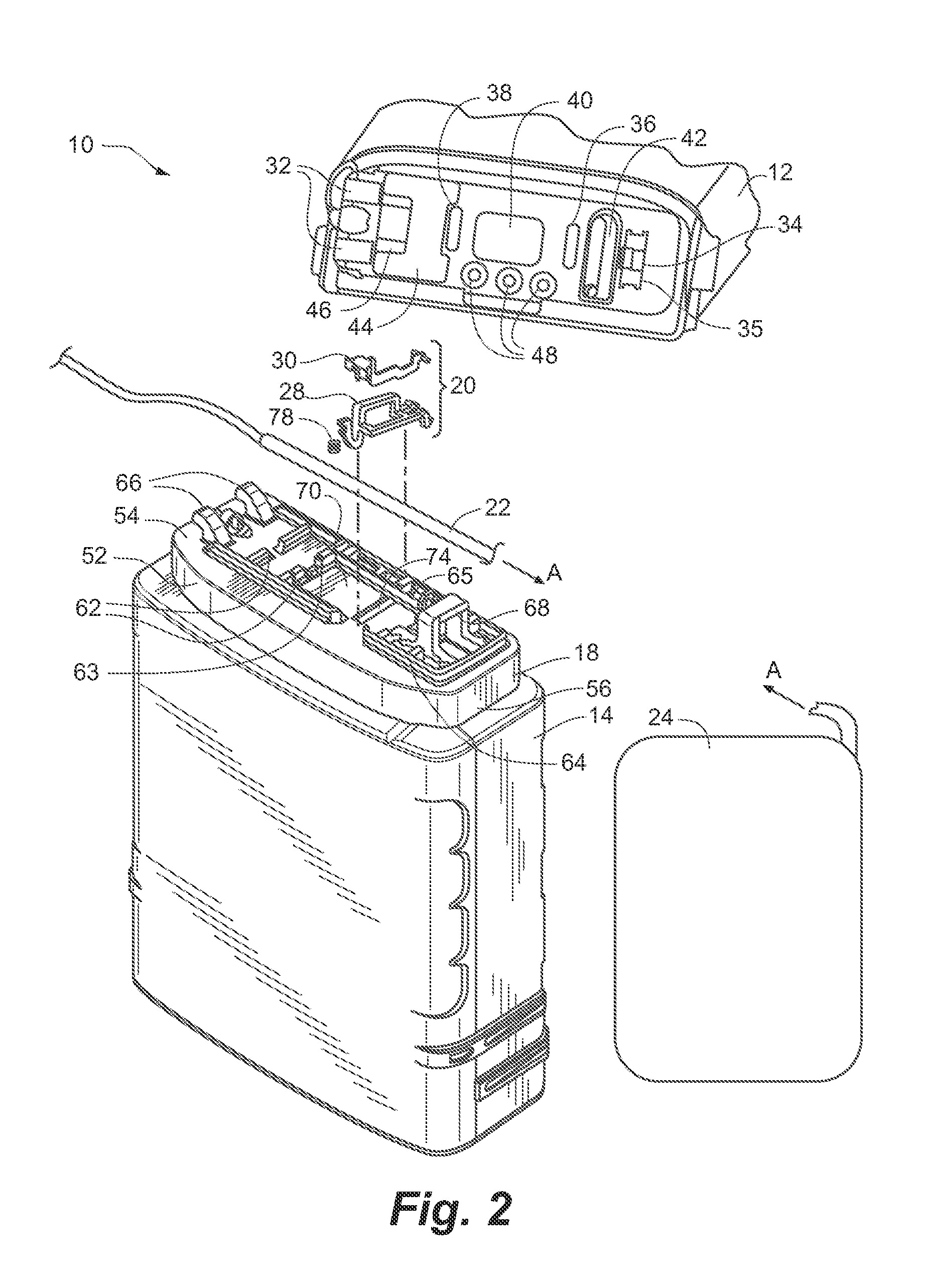
[0027]In various embodiments of this invention an apparatus and method are disclosed for an improved flow stop device for infusion pumps. FIG. 1 generally depicts an example of an infusion pump 10 which includes a control module 12 and a cassette 14 in coupled arrangement. Specifically, the cassette 14 includes a container portion 16 which defines a space for housing and generally enclosing a bag or reservoir of medication and a pressure plate 18 extending across the upper surface of the cassette. Control module 12 and cassette 14 may be of various designs, sizes and shapes that are not limited to the sizes or types of pumps or cassettes as depicted in the figures. Infusion pumps may include peristaltic pumps, roller pumps, expulsor pumps, or other pumps. Ca...


PUM

PropertyMeasurementUnit
pressureaaaaaaaaaa
movementaaaaaaaaaa
forceaaaaaaaaaa

Abstract

An embodiment is directed to pressure plate for attachment to an infusion pump, where the pressure plate includes a tubing support surface at least partially surrounded by a raised perimeter support. The pressure plate includes a plurality of guide structures extending from the raised perimeter support that define a passageway for an infusion pump tube. Additionally an attachable flow stop assembly is included that includes an attachable occlusion arch and an attachable flow stop arm. The attachable occlusion arch includes a plurality of tab structures that couple to the raised perimeter support. The occlusion arch further includes an aperture configured to surround an infusion pump tube threaded therethrough. The attachable flow stop arm is operatively coupled to the raised perimeter support adjacent the attachable occlusion arch in a spring-biased fashion such that the aperture in the occlusion arch may be selectively occluded by the flow stop arm.

Description

RELATED APPLICATION[0001]This application is a division of application Ser. No. 13 / 443,390 filed Apr. 10, 2012, which is hereby fully incorporated herein by reference.FIELD OF THE INVENTION[0002]The present invention relates to features for governing the flow of fluid in medical infusion pumps. More specifically, this invention relates to a flow stop insert for an infusion pump having an improved design for operation and manufacture.BACKGROUND OF THE INVENTION[0003]Infusion pumps, drug pumps and medication delivery devices are well-known and widely used throughout the world today. Intravenous infusion pumps were developed decades ago to pump fluid medicants or nutrients through a tube set to a patient in connection with treatment of a medical condition. Infusion pumps include peristaltic pumps, roller pumps, or expulsor pumps, for example. Various pumps include a reusable control module that is detachably coupled to a pressure plate on the top of a disposable or reusable fluid reser...

Claims


Application Information

Patent Timeline
Patent Type & Authority Applications(United States)
IPC IPC(8): A61M5/168
CPCA61M2207/00A61M5/16804A61M5/14228A61M5/14232A61M5/14244A61M39/281A61M2205/12A61M2205/123Y10T29/49412
Inventor ROBERT, RENEECOTE, STEVETAYLOR, JEFF
Owner SMITHS MEDICAL ASD INC
Why Eureka
Try Eureka