
Impeller of a pump unit and corresponding pump unit

A technology of a pump device and an impeller is applied to the impeller of a sewage pump device, and the field of the pump device with the impeller can solve the problems of reducing the efficiency of the pump device and the like.

Inactive Publication Date: 2008-12-17
GRUNDFOS MANAGEMENT AS
View PDF0 Cites 7 Cited by
  • Summary
  • Abstract
  • Description
  • Claims
  • Application Information

AI Technical Summary

Problems solved by technology

However these solutions have the disadvantage of reducing the efficiency of the pumping device

Method used


Image

  • Impeller of a pump unit and corresponding pump unit
  • Impeller of a pump unit and corresponding pump unit

Examples


Embodiment Construction

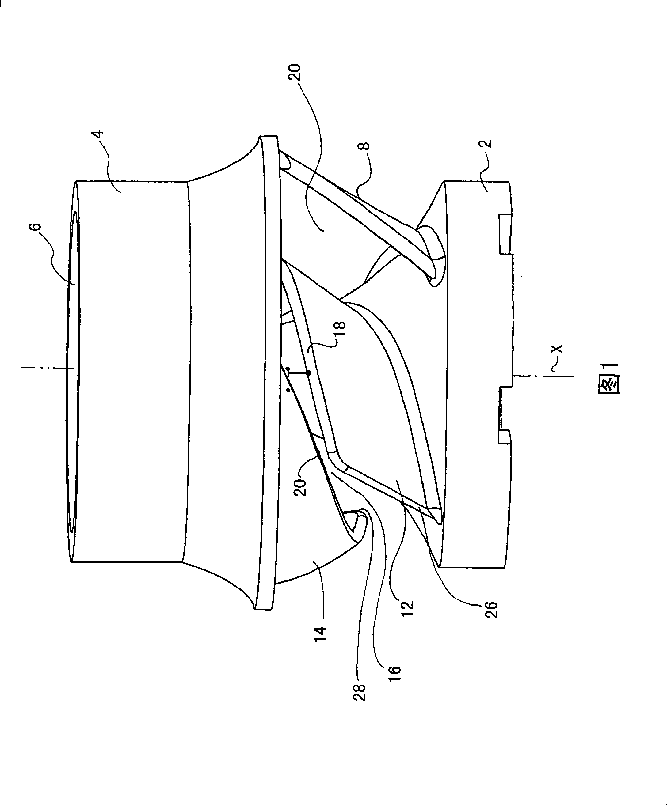
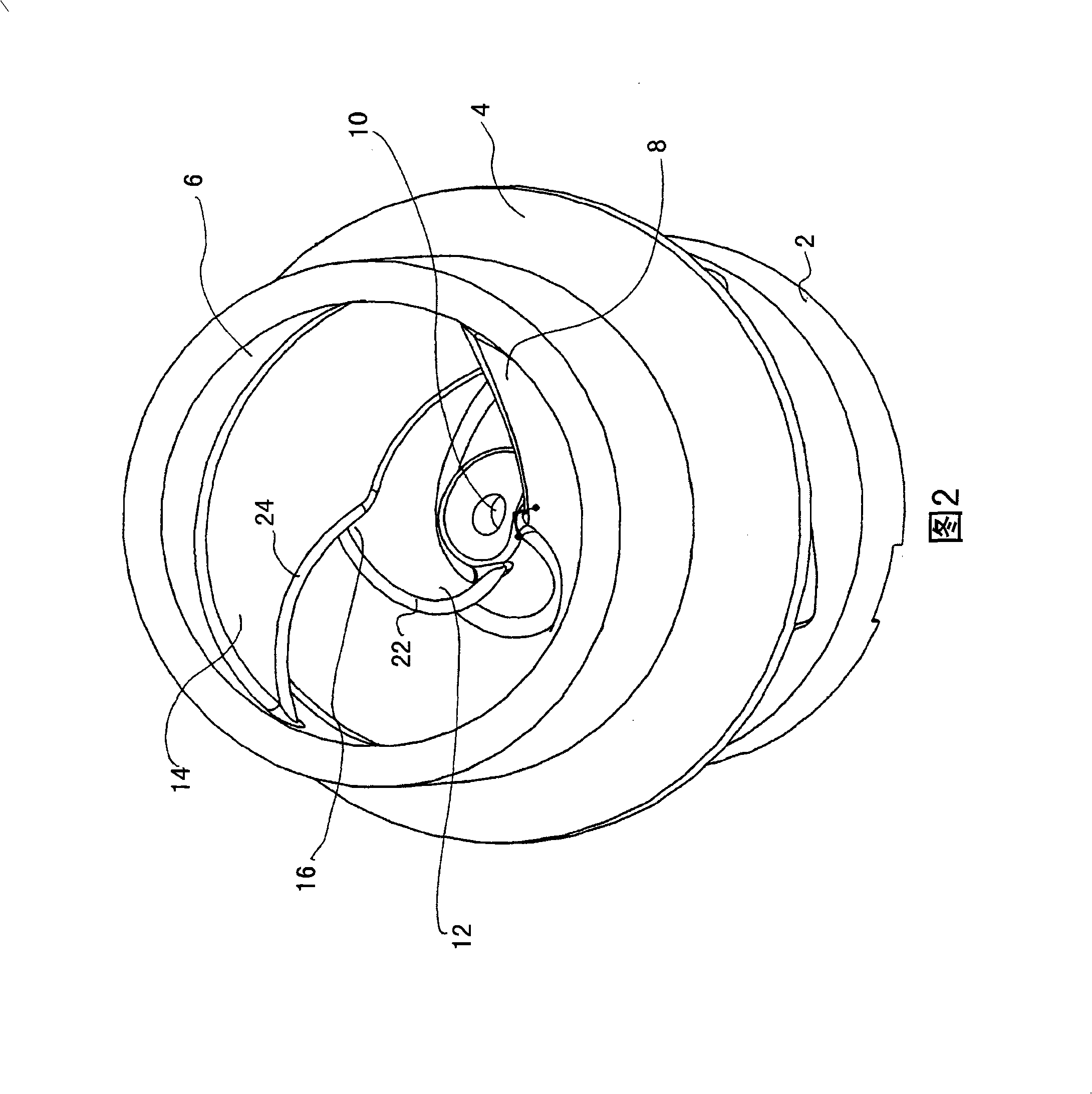
[0025] The impeller has two end caps 2 and 4 , wherein the end cap 4 has a central inlet 6 . When the impeller rotates about the axis of rotation X, the fluid to be conveyed is sucked in through the inlet 6 .

[0026] Between the two end caps 2 and 4 there is provided a continuous first vane 8 which firmly connects the end caps 2 and 4 to each other, thereby keeping the end caps 2 and 4 in a certain direction along the longitudinal axis X. spacing. In addition, the blades 8 also serve to rotate the end cap 4 together with the end cap 2 around the longitudinal axis X. The drive shaft of the impeller acts on the central hole 10 in the end cover 2 so that the drive torque is transmitted to the end cover 2 and from the end cover 2 to the end cover 4 via the blades 8 .

[0027] Instead of having continuous blades 8 , the impeller can also have blades of split construction, which consist of two blade parts 12 and 14 . The blade part 12 is firmly connected to the end cover 2 , and...


PUM


Abstract

The invention relates to an impeller for a pump unit, in particular for a waste water pump unit, having two cover plates (2, A) which are spaced apart from one another in the axial direction (X) and are connected to one another by means of at least one connecting element (8), and having at least one blade (12, 14) which is arranged between the two cover plates (2, 4) and extends from an inner diameter of the impeller to an outer diameter of the impeller, wherein the blade (12, 14) has a continuous slot (16) which extends from that edge (22, 24) of the blade (12, 14) which is situated at the inner diameter to that edge (26, 28) of the blade (12, 14) which is situated at the outer diameter, and to a pump unit having an impeller of said type.

Description

technical field [0001] The invention relates to an impeller for a pump arrangement, in particular for a sewage pump arrangement, and a pump arrangement having such an impeller. Background technique [0002] Wherever contaminated fluids are conveyed, ie, for example in the field of sewage conveyance, there is the problem of fouling of the pump devices used. In particular, long-fibrous dirt can adhere to the blades of the impeller of the pump device for a long time and can affect the operation of the pump device and even cause damage to the pump device in special cases. For this reason, impellers with only one flow channel are commonly used in sewage pumps, which impellers do not have edges or walls on which long-fibrous dirt can adhere. Another possible solution to avoid this problem is to design the impeller to be open so that dirt cannot adhere to the blades. However, these solutions have the disadvantage of reducing the efficiency of the pump arrangement. Contents of t...

Claims


Application Information

Patent Timeline
Patent Type & Authority Applications(China)
IPC IPC(8): F04D29/22F04D29/24F04D7/04
CPCF04D29/2288F04D29/24
Inventor 拉塞·伊尔韦斯于利·科尔佩拉·海基
Owner GRUNDFOS MANAGEMENT AS
Learn More