Vacuum commutation apparatus and methods

Active Publication Date: 2017-01-26
CURT G JOA
View PDF0 Cites 6 Cited by
  • Summary
  • Abstract
  • Description
  • Claims
  • Application Information

AI Technical Summary

Benefits of technology

[0024]In such a puck system, ambient air can flow from the inside of the puck outward to: 1) eliminate or minimize overlapping low pressure zones which in turn eliminates or minimizes in-rushes of air at the edges of the patch; 2) results in an airflow direction that is approximately perpendicular to the surface to which the discrete element is riding upon. Such a puck system also can utilize micro-pores to: 1) reduce airflow requirements; 2) provide more complete sealing of the pores and thereby increases holding force on the discrete article; and 3) minimize dead zones between pores to minimize the potential for discrete article edge flip backs.
[0025]A process is disclosed that optimizes repeatability of discrete article transfer from one carrier device

Problems solved by technology

Along with significant increase in vacuum demand comes the expense of powering conventi

Method used


Image

  • Vacuum commutation apparatus and methods
  • Vacuum commutation apparatus and methods
  • Vacuum commutation apparatus and methods

Examples


Example

[0042]Although the disclosure hereof is detailed and exact to enable those skilled in the art to practice the invention, the physical embodiments herein disclosed merely exemplify the invention which may be embodied in other specific structures. While the preferred embodiment has been described, the details may be changed without departing from the invention, which is defined by the claims.

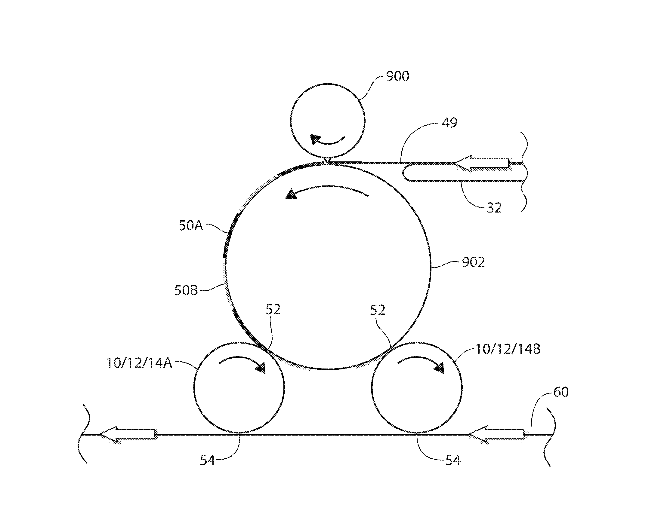
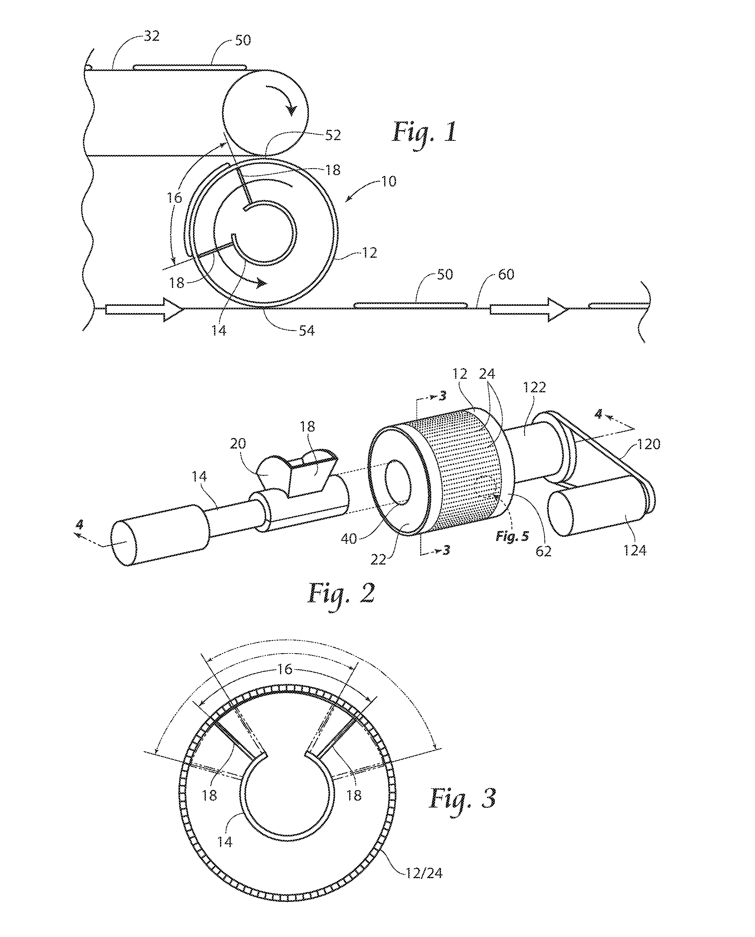
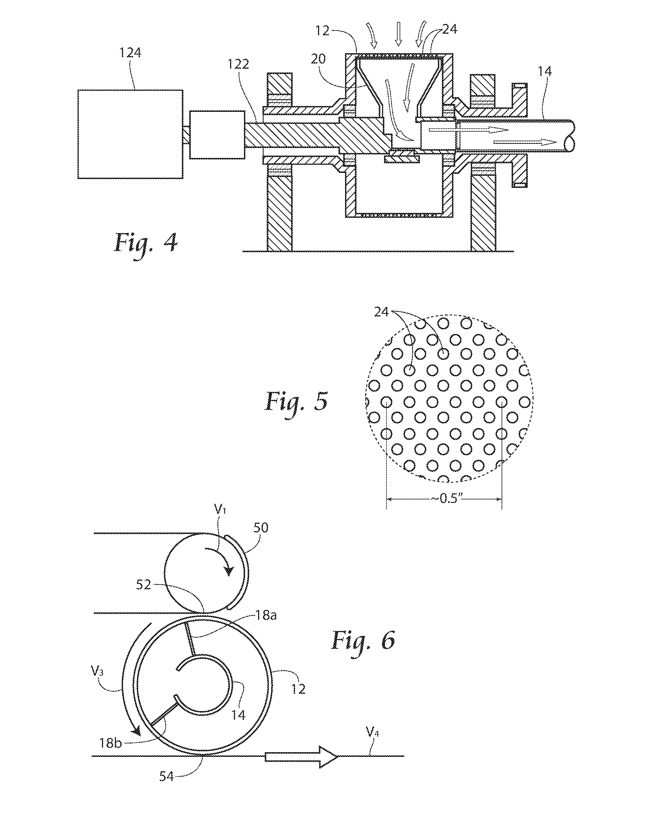
[0043]Referring now to FIG. 1, a side view of a system 10 comprising a porous roll 12 and internal independently rotatable vacuum manifold 14 carrying a discrete component of a disposable article 50 between an acquisition point 52 and a deposition point 54 is shown.

[0044]A conveyor 32 carries discrete components 50 towards an acquisition point 52. At the acquisition point 52, control of the discrete component 50 is handed off to a porous roll and vacuum manifold combination 10. Vacuum is drawn through the vacuum manifold 14, and in particular through a hollow shaft of the manifold 14, towards a va...


PUM

PropertyMeasurementUnit
Fractionaaaaaaaaaa
Fractionaaaaaaaaaa
Surface areaaaaaaaaaaa

Abstract

The present invention provides a method and apparatus for transporting a discrete element. A preferably rotatably driven vacuum commutation zone (or internal vacuum manifold), preferably internal to a preferably independently driven porous vacuum roll or drum is disclosed. The vacuum manifold applies vacuum through pores in the driven porous vacuum roll or puck in order to hold material against an external surface of the vacuum roll or puck. By independently controlling the vacuum commutation zone and the driven porous surface, unique motion profiles of the vacuum commutation zone relative to the driven porous surface can be provided. Micro vacuum commutation port structures are also disclosed.

Description

RELATED APPLICATIONS[0001]This application claims the benefit of provisional application Ser. No. 62 / 196,736 filed 24 Jul. 2015. This application also claims the benefit of provisional application Ser. No. 62 / 248,155 filed 29 Oct. 2015.BACKGROUND OF THE INVENTION[0002]The present invention relates to disposable hygiene products and more specifically, to methods and apparatuses for processing disposable hygiene products such as baby diapers, adult diapers, disposable undergarments, incontinence devices, sanitary napkins and the like.[0003]More specifically, the invention relates to novel vacuum commutation. A puck or drum is used in a novel way with a novel vacuum applicator. Vacuum, which for the purpose of the following description is defined to mean air pressure that is lower than ambient air pressure, is used in many parts of a diaper manufacturing process. For instance, during pulp core formation, ambient air flows through the surface of the forming pockets to the vacuum manifol...

Claims


Application Information

Patent Timeline
IPC IPC(8): A61F13/15B65H20/12
CPCA61F13/15764B65H20/12B65H2801/57B65H2408/215A61F2013/15926B65H39/14B65H2406/361B65H29/243B65H5/226B65H2301/4473B65G29/02B65G47/915B65G47/848B65H2220/02B65G39/02B65H27/00B65H2404/1362B65H2404/1363B65H2406/332
Inventor INGOLE, SUDEEPPELLAND, JON ALLEN
Owner CURT G JOA
Why Eureka
Try Eureka