
System and method of trapping for correcting for separation misregistration in color printing

a color printing and misregistration technology, applied in the field of system and method of trapping for correcting for color printing separation misregistration, can solve the problems of inability to achieve a zero width boundary between regions of different colors, mechanical problem of misregistration, and inability to precisely lay color separations

Inactive Publication Date: 2006-10-17
XEROX CORP
View PDF23 Cites 37 Cited by
  • Summary
  • Abstract
  • Description
  • Claims
  • Application Information

AI Technical Summary

Benefits of technology

[0059]In accordance with other aspects of the invention, the above defined system may optionally be limited to work at detected edges in an image. Additionally, sinc

Problems solved by technology

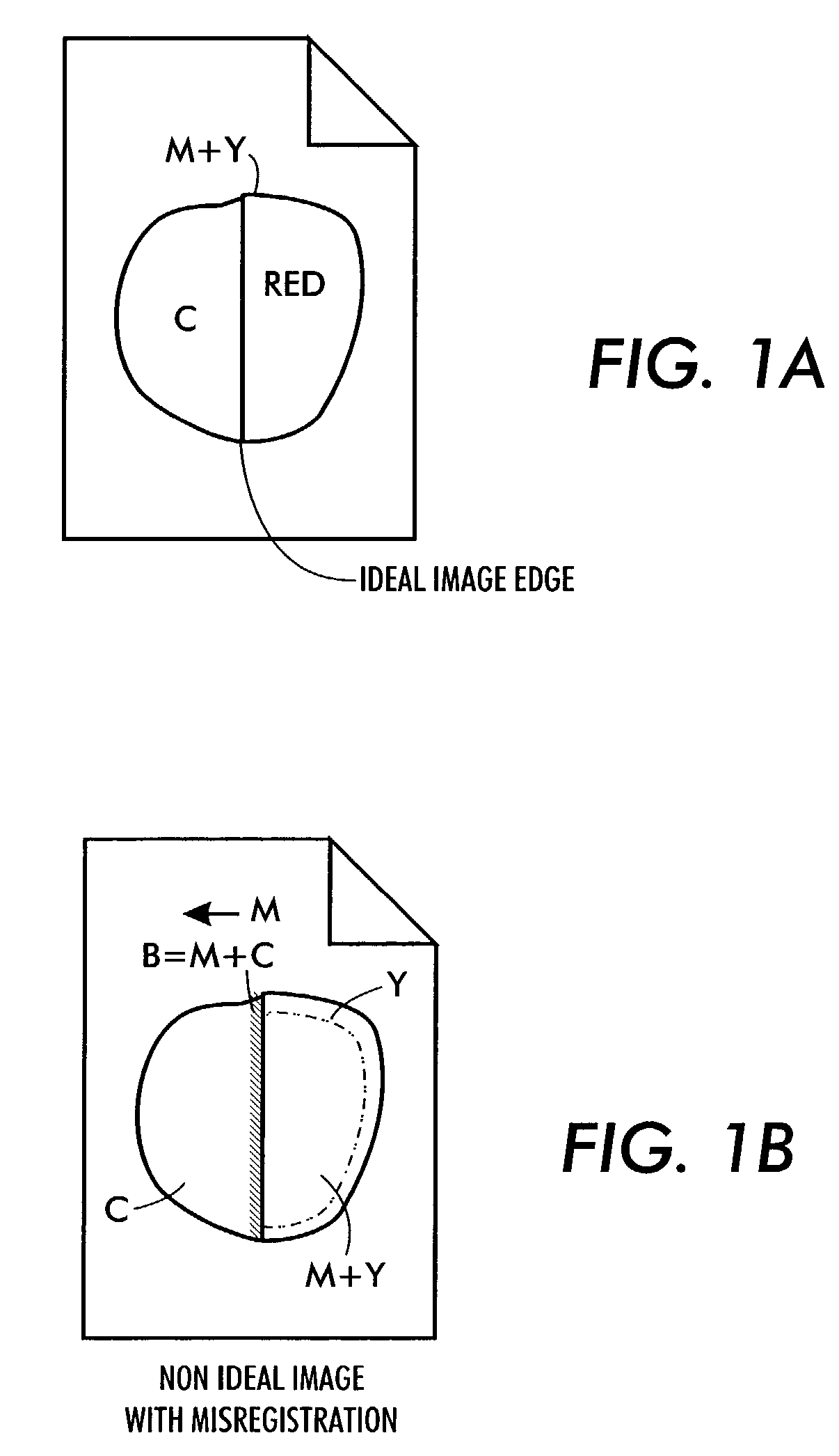
In practice therefore, the realization of a zero width boundary between regions of different color is impossible as a result of small but visible misregistration problems from one printed separation to another.
The error is manifested as a “light leak” or as a visible boundary region of an undesired color.
The problem of misregistration is a mechanical problem, almost always existing in printing systems.
The problem arises because color separations are not laid exactly where intended, due to inherent imperfections in any separation registration process.
It is somewhat correctable by mechanical registration methods; however it is rarely completely correctable.
In expensive, high end printing processes, customers have high expectations that misregistration artifacts will not be visible.
In inexpensive, low end printers, mechanical registration techniques are so expensive as to make correction or trapping essential.
As will become apparent, different printing technologies have distinct misregistration artifacts.
However, xerographic printing tends to have more misregistration in a single direction.
Furthermore, traps are created with this package using pre-set rules, and are not editable by a user without the requirement for repeating the computation.
If they overlap existing objects, they are trapped against them.
Thus traps are introduced as objects are processed, possibly causing a region to be trapped and re-trapped as the traps are covered up.
Without a means for configuring the automatic trap selection method, a user is forced to rely on manual trap specification, even for routine operations.
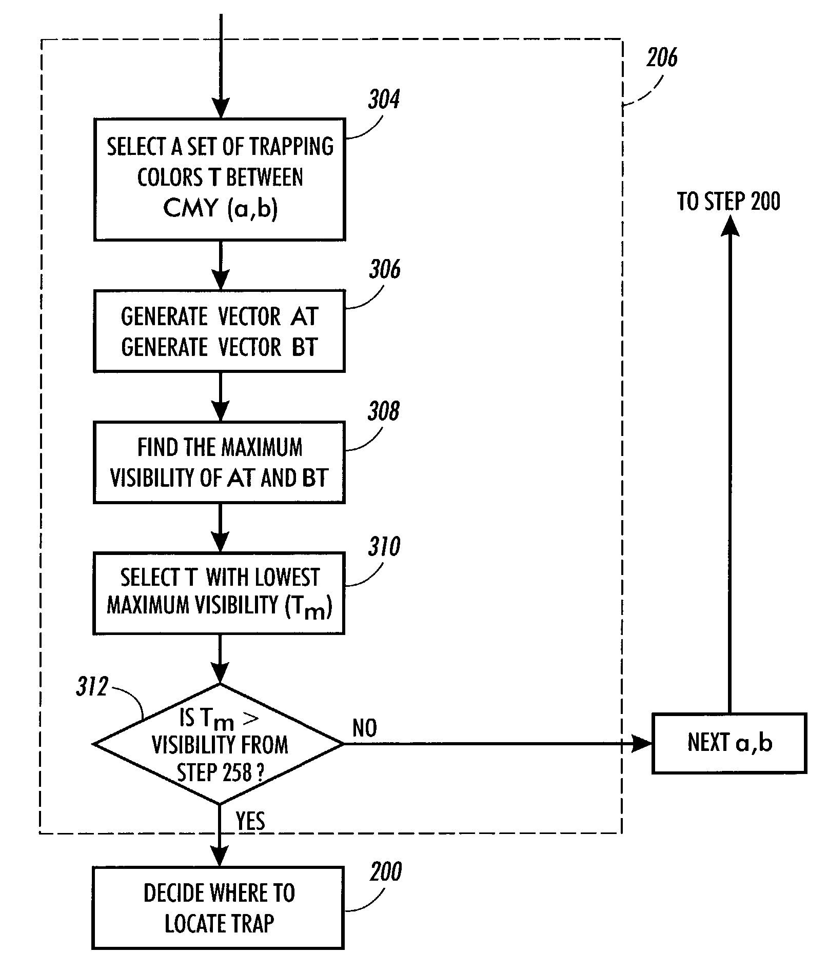
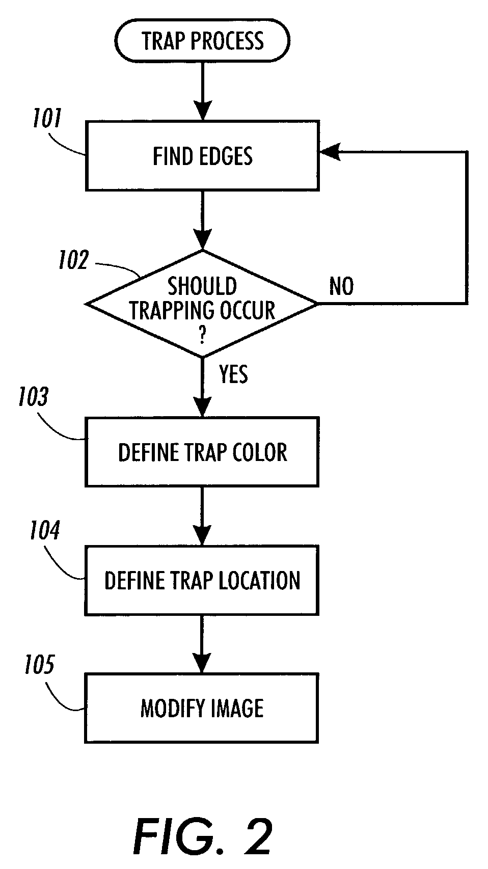
The specification of a trap at the boundary between two color regions does not in itself eliminate the misregistration of printing plates, but reduces the visual effect of misregistration within the trap zone through proper choice of the trap operation.
Generally, these values are not used in more precise measures of human perception, however.
As a result, the use of luminance or lightness contrast across an edge does not always provide an adequate indicator of whether a gap created by misregistration will be visible at the edge.
Yet another problem associated with trapping is where to put the trap color.
Specifically, it is very hard to see fine detail in blue-yellow variation.

Method used


Image

  • System and method of trapping for correcting for separation misregistration in color printing
  • System and method of trapping for correcting for separation misregistration in color printing
  • System and method of trapping for correcting for separation misregistration in color printing

Examples


Embodiment Construction

[0072]Referring now to the drawings where the showings are for the purpose of describing an embodiment of the invention and not for limiting same, a basic image processing system is shown in FIG. 1, where gray image data may be characterized as image signals, each pixel of which is defined at a single level or optical density in a set of ‘c’ optical density levels.

[0073]As used herein, a “pixel” refers to an image signal associated with a particular position in an image, having a density between a minimum and a maximum. Accordingly, intensity and position define pixels. In the particular color system to be discussed, color documents are represented by multiple sets of image signals, each set (or separation) represented by an independent channel, which is usually processed independently. A “color image” as used herein is therefore a document including at least two separations, or sometimes more than 4 separations (sometimes referred to as “hifi color”. Each separation provides a set ...


PUM


Abstract

A color printing system which deposits colors on a separation by separation basis provides trapping to correct misregistration between printer output colors due to imperfect placement of the separation colors. The system includes a trapping calculation processor, determining trapping requirements based on visibility, measured in a color space in which equivalent color differences in human color perception are approximately equivalent values.

Description

CROSS REFERENCE[0001]This is a divisional of application Ser. No. 09 / 176,969 filed Oct. 22, 1998 now abandoned.[0002]This invention relates to electronic processing of graphic images to produce multi-color prints using multiple separations. Typically, four process color inks, cyan, magenta, yellow and black are used, to print multiple separations, which tend to have minor misregistration problems. Trapping is a process for adjusting images to correct for misregistration. The present invention is directed to a process for controlling trapping, based on the appearance of any misregistration artifacts against the remainder of the image.BACKGROUND OF THE INVENTION[0003]The layout of a page or graphic image depends upon combining “structured graphics” according to a pre-established graphic design. The structured graphics are contiguous regions of color, usually represented in a plurality of separation images, in turn representing a succession of graphic objects imaged on the printing med...

Claims


Application Information

Patent Timeline
IPC IPC(8): G06F15/00G06K9/00G06K9/36G06F3/12G03G15/01G06T1/00H04N1/46H04N1/58H04N1/60
CPCH04N1/58
Inventor KLASSEN, R. VICTOR
Owner XEROX CORP
Learn More