Process for assembling connector

a technology for assembling and connectors, applied in the direction of coupling device connections, contact member manufacturing, securing/insulating coupling contact members, etc., can solve the problems of severe deterioration in production efficiency, so as to improve production efficiency

Inactive Publication Date: 2006-10-24
YAZAKI CORP
View PDF11 Cites 49 Cited by
  • Summary
  • Abstract
  • Description
  • Claims
  • Application Information

AI Technical Summary

Benefits of technology

[0023]It is therefore an objective of the present invention to solve the above problem and to provide a process and device for assembling a connector, by which the production efficiency can be improved by preventing the problem of insertion

Problems solved by technology

When such a problem takes place in the automatic assembly machine, which manufactures a wiring harness, the machine detects the abnormality and halts its operation, causing a deterioration in the production efficiency.
When such a problem frequently takes pl

Method used


Image

  • Process for assembling connector
  • Process for assembling connector
  • Process for assembling connector

Examples


Embodiment Construction

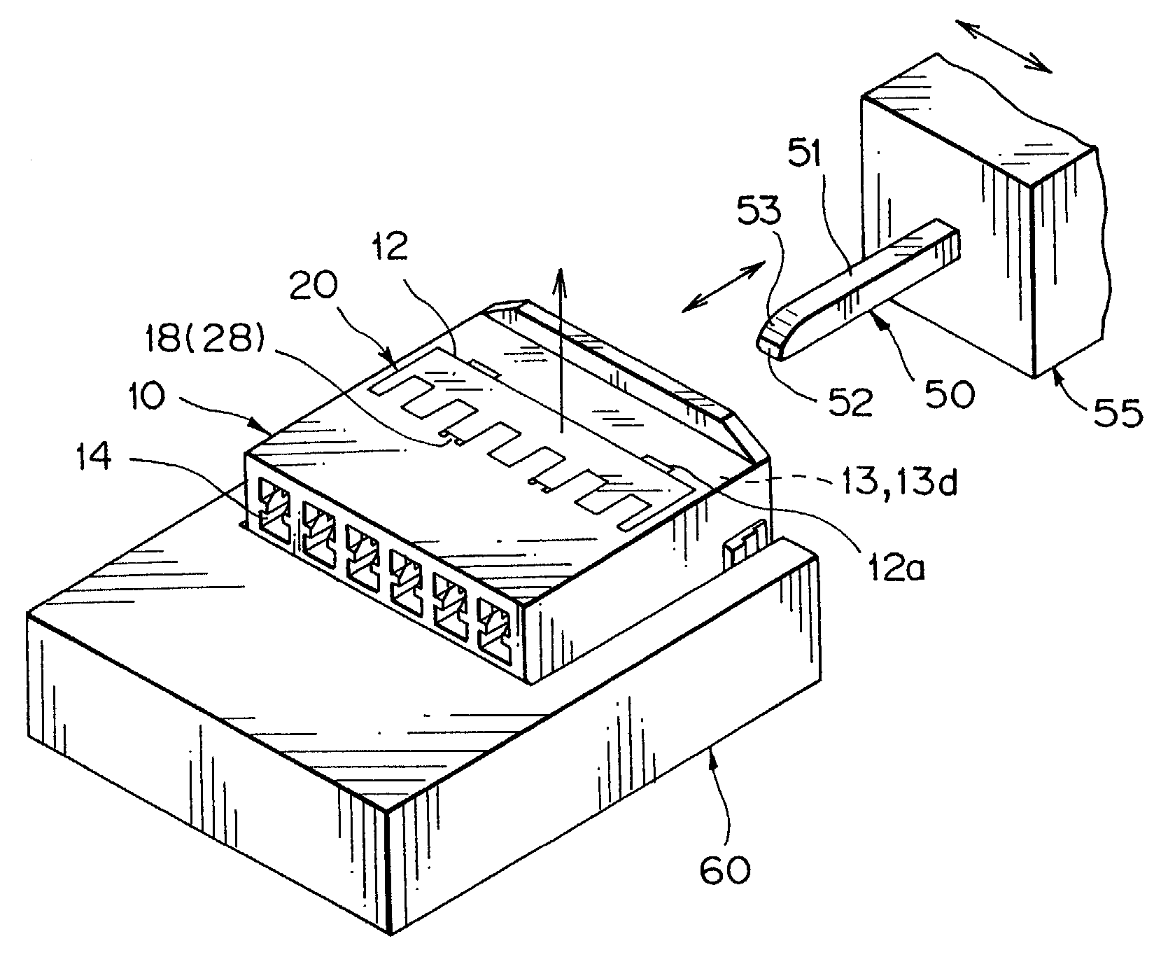
[0059]In the following, a preferred embodiment of a process and device for assembling a connector according to the present invention will be explained in detail with reference to the attached drawings. The same reference numeral, which is used in the explanation of the prior art described above, is used for a component or part in the preferred embodiment if such a component or part corresponds to one in the prior art in its name, and the detailed explanation for them is omitted.

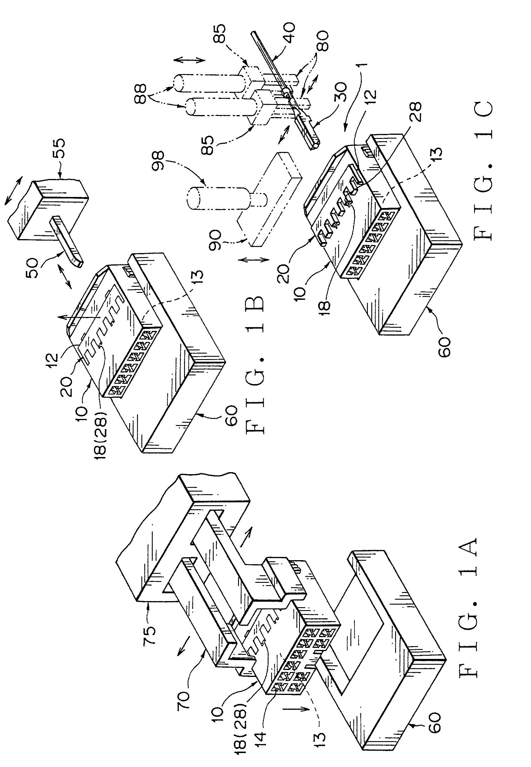
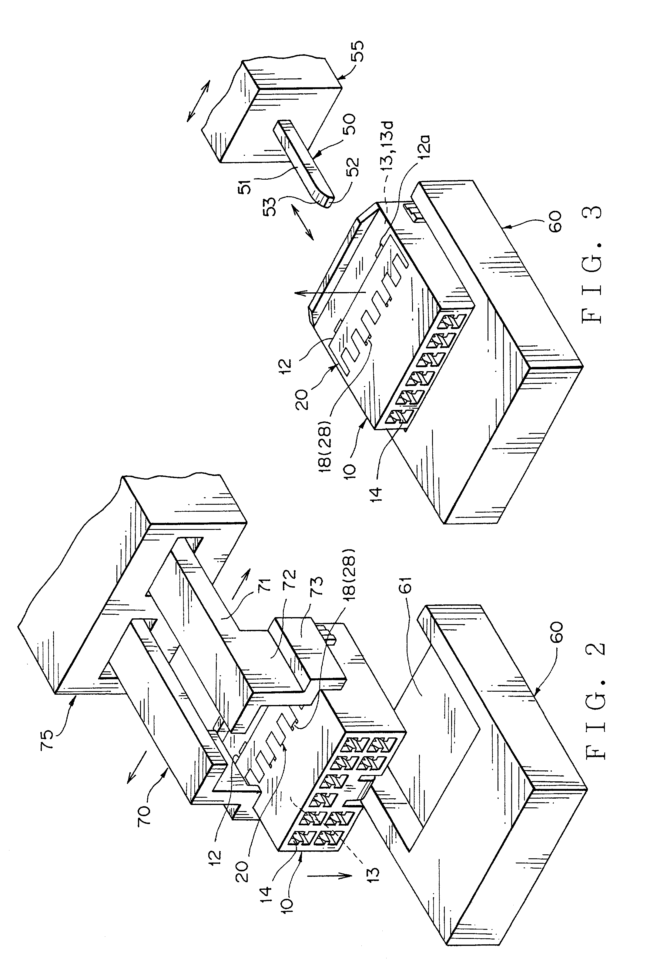
[0060]FIG. 1A is a perspective view illustrating a preferred embodiment of a process and device for assembling a connector according to the present invention, in which a connector housing is placed on a base. FIG. 1B is a perspective view illustrating a preferred embodiment of a process and device for assembling a connector according to the present invention, in which a jig rod is inserted into a connector housing. FIG. 1C is a perspective view illustrating a preferred embodiment of a process and device for a...


PUM


Abstract

A process for assembling a connector is provided, by which the production efficiency can be improved by preventing the problem of insertion error from occurring in a step of terminal insertion into a connector housing in the manufacturing process of the wiring harness by using an automatic assembly machine or in a step of the operation by the human hands. The process includes the steps of: provisionally locking the spacer in the connector housing; inserting ajig rod into the connector housing before inserting the terminal into the connector housing, the jig rod being for releasing the locking of the spacer which is completely locked in the connector housing; pulling the jig rod out from the connector housing; and inserting the terminal into the connector housing.

Description

BACKGROUND OF THE INVENTION[0001](1) Field of the Invention[0002]The present invention relates to a process and device for assembling a connector, by which a terminal is securely fixed in a connector housing no matter whether a spacer is provisionally or completely mounted in the connector housing.[0003](2) Description of the Related Art[0004]Each of FIGS. 10 and 11 is a longitudinal cross sectional view illustrating an example of a conventional assembly of a double locking connector.[0005]The double locking connector 1 includes a connector housing 10, spacer 20 and female terminal 30 with these parts being assembled therein.[0006]The connector housing 10 is formed with circumferential walls 11 and includes a spacer receiving chamber 12, spacer insertion opening 12, terminal receiving chamber 13, rear opening 13d and terminal insertion opening 14. The same reference numeral 12 is used for the spacer receiving chamber 12 and spacer insertion opening 12 for convenience. The terminal r...

Claims


Application Information

Patent Timeline
IPC IPC(8): H01R43/20H01R13/42H01R13/436
CPCH01R13/4362H01R43/20Y10T29/49222Y10T29/49204Y10T29/49169Y10T29/53217Y10T29/49208Y10T29/532Y10T29/53209Y10T29/53213
Inventor YAMANASHI, MAKOTOSUZUKI, SHOGO
Owner YAZAKI CORP
Why Eureka
Try Eureka