
Method and apparatus for autonomous detonation delay in munitions

a technology of detonation delay and munitions, applied in the direction of electric fuzes, lighting and heating apparatus, combustion process, etc., can solve the problem of significant detonation of the warhead

Active Publication Date: 2006-10-24
NORTHROP GRUMMAN SYST CORP
View PDF26 Cites 41 Cited by
  • Summary
  • Abstract
  • Description
  • Claims
  • Application Information

AI Technical Summary

Benefits of technology

The present invention relates to a detonation timing apparatus for an explosive projectile. The apparatus includes an initiation sensor, an impact sensor, and a controller. The controller senses the initiation and impact events and determines the impact velocity estimate, which is used to determine the detonation delay and generate the detonation event at a more optimum penetration depth. The invention also includes a fuze for the explosive projectile and a method for determining the detonation time. The technical effect of the invention is to improve the accuracy and efficiency of detonation timing for explosive projectiles.

Problems solved by technology

A fixed delay may cause the warhead to detonate significantly earlier than or later than this optimum penetration depth is reached.

Method used


Image

  • Method and apparatus for autonomous detonation delay in munitions
  • Method and apparatus for autonomous detonation delay in munitions
  • Method and apparatus for autonomous detonation delay in munitions

Examples


Embodiment Construction

[0022]In the following description, circuits and functions may be shown in block diagram form in order not to obscure the present invention in unnecessary detail. Conversely, specific circuit implementations shown and described are exemplary only and should not be construed as the only way to implement the present invention unless specified otherwise herein. Additionally, block definitions and partitioning of logic between various blocks is exemplary of a specific implementation. It will be readily apparent to one of ordinary skill in the art that the present invention may be practiced by numerous other partitioning solutions. For the most part, details concerning timing considerations and the like have been omitted where such details are not necessary to obtain a complete understanding of the present invention and are within the abilities of persons of ordinary skill in the relevant art.

[0023]In this description, some drawings may illustrate signals as a single signal for clarity o...


PUM


Abstract

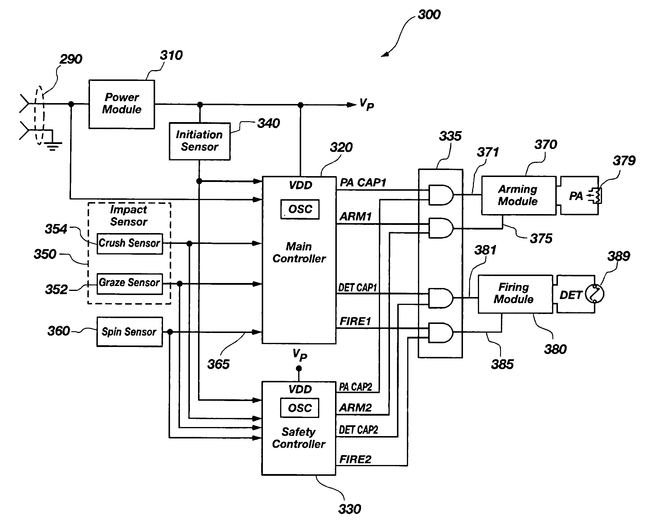
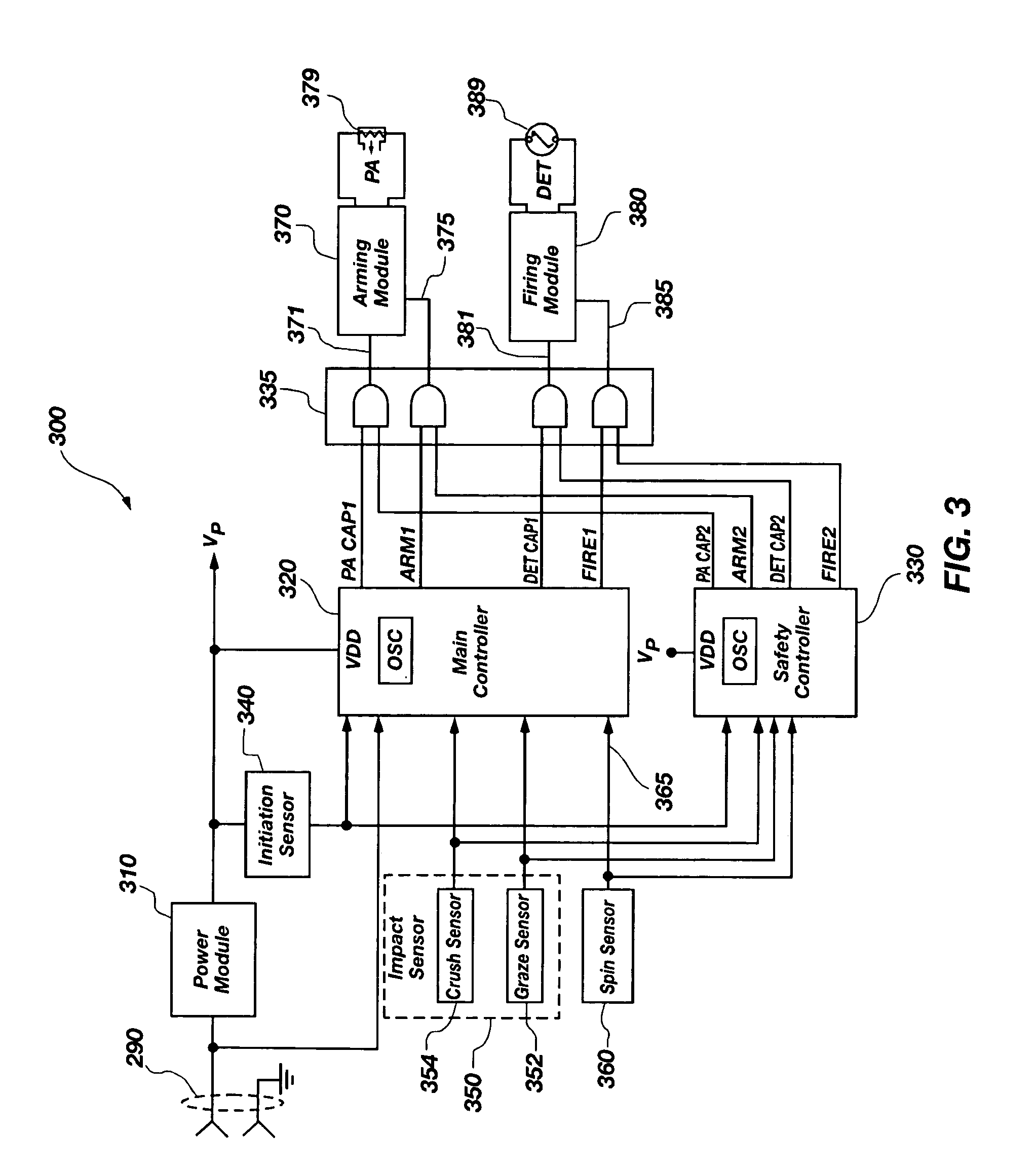
A detonation timing apparatus and method of determining a detonation time is disclosed. The detonation timing apparatus comprises an initiation sensor, at least one impact sensor, and at least one controller. The at least one controller may be configured for sensing an initiation event associated with the initiation sensor and sensing an impact event associated with the at least one impact sensor. The at least one controller is further configured for determining an impact velocity estimate proportional to a temporal difference between the initiation event and the impact event, using the impact velocity estimate to determine the detonation delay, and generating the detonation event at the detonation delay after the impact event. The timing apparatus and method of determining a detonation time may be incorporated in a fuze, which may be incorporated in an explosive projectile.

Description

CROSS REFERENCE TO RELATED APPLICATIONS[0001]The present application is related to concurrently filed U.S. patent application Ser. No. 10 / 994,497 entitled METHOD AND APPARATUS FOR SPIN SENSING IN MUNITIONS.BACKGROUND OF THE INVENTION[0002]1. Field of the Invention[0003]This invention relates generally to fuzes for explosive devices and more particularly to determining a detonation time related to when an explosive device impacts with a target.[0004]2. Description of Related Art[0005]Explosive projectiles must be capable of being handled safely under considerable stress and environmental conditions. In addition, explosive projectiles must be capable of detonating at the proper time. Depending on the application, this proper time may be before impact, at a specific point during flight, during impact, or at some time delay after impact. As used herein the terms “warhead,”“explosive device,” and “explosive projectile” are generally used to refer to a variety of projectile type explosive...

Claims


Application Information

Patent Timeline
Patent Type & Authority Patents(United States)
IPC IPC(8): F42C19/06
CPCF42C9/147F42C11/065F42C17/04
Inventor DAVIS, MARTIN R.NELSON, CARLTOMES, MARK J.
Owner NORTHROP GRUMMAN SYST CORP
Learn More