Tool holder with integral coolant channel and locking screw therefor

a tool holder and coolant channel technology, applied in the field of machine tools, can solve the problems of limited amount of coolant having any practical effect on the cutting insert, cutting edge only being exposed to the coolant to a very limited degree, and plastic deformation of the cutting inser

Inactive Publication Date: 2006-10-24
KENNAMETAL INC
View PDF13 Cites 94 Cited by
  • Summary
  • Abstract
  • Description
  • Claims
  • Application Information

AI Technical Summary

Benefits of technology

[0010]In yet another embodiment of the invention, the cutting tool comprises a locking screw having a cap, a threaded shank, and a shoulder between the cap and the threaded shank, the locking screw further comprises at least one annular seal in an axially spaced relation to a shoulder. The annular seal is engageable with the cutter body with sufficient compression to provide at least one seal between the cap and the cutter body while providing a dampening effect between the locking screw and the cutter body. The compression of the annular seal is dependent on the axially spaced relation between the seal and the shoulder.

Problems solved by technology

When large cutting forces act on the cutting insert, this phenomenon entails a risk that the cutting insert will be subject to plastic deformation, in particular, in the proximity of the cutting edge, where insert breakage can result.
This method of supply, however, results in only a very limited amount of the coolant having any practical affect on the cutting insert.
That is, because of the presence of the chips, the cutting edge is only exposed to the coolant to a very limited degree.
However, when the cooling liquid is applied at normal pressures, this procedure does not result in any significant improvement in cooling effect compared to the aforementioned methods because the cooling liquid does not reach that part of the cutting insert which is hottest and which is exposed to the greatest mechanical load.
Thus, a clear risk exists of the cutting insert becoming plastic because of excessively high temperatures.
The effect of the cooling can certainly be increased considerably by increasing the pressure of the cooling liquid to very high levels but the equipment required to raise the cooling liquid pressure to this level is very complicated and expensive.
Working with extremely high fluid pressure is furthermore, in practice, is undesirable.
Common to all the solutions to the problem indicated above, which are based on transverse or open channels or grooves for feeding the coolant, is that the channels weaken the cutting insert in the cutting edge area and there is a risk that the channels will be blocked by the hot material of the chip which sticks to the insert surface.
Furthermore, the existence of the channels or grooves limits the possibilities to design the cutting insert with an optimal chip breaker geometry.
However, this cavity weakens the cutting insert to such a large degree that its use is not practical when exposed to typical cutting forces.
This would result in a longer life for the insert.

Method used


Image

  • Tool holder with integral coolant channel and locking screw therefor
  • Tool holder with integral coolant channel and locking screw therefor
  • Tool holder with integral coolant channel and locking screw therefor

Examples


Embodiment Construction

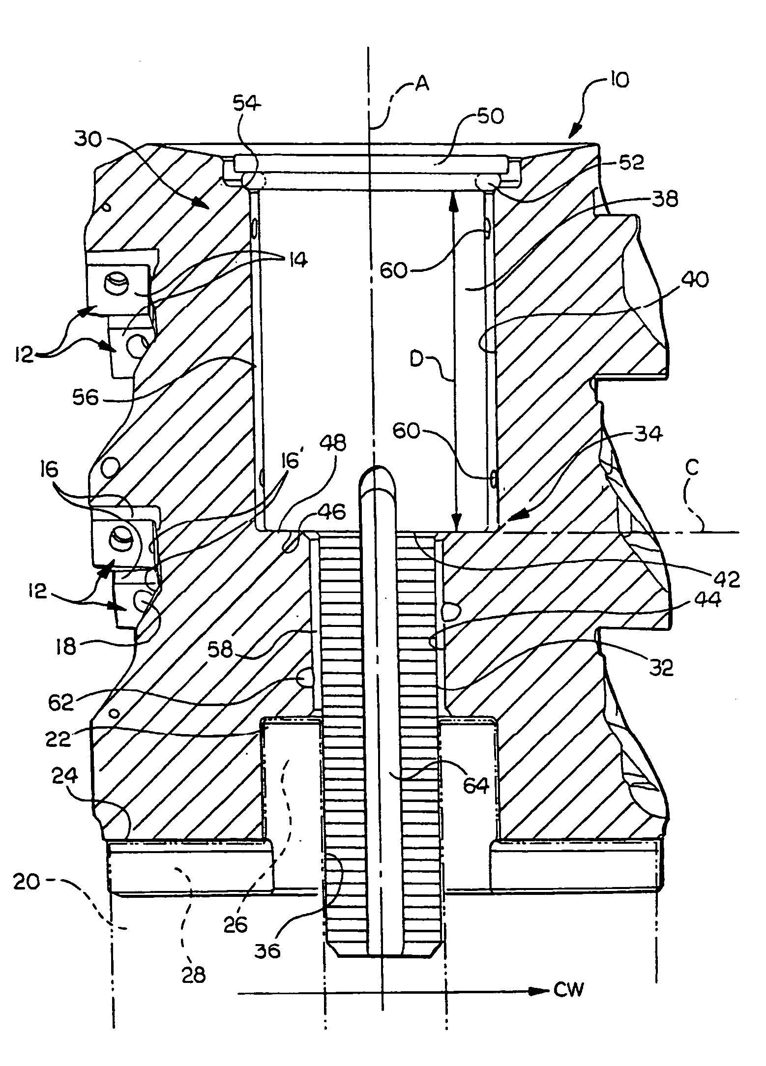
[0015]With reference now to the drawings, wherein like numerals designate like components throughout all of the several figures, there is illustrated in FIG. 1 a tool holder or cutter body, as generally indicated at 10. The cutter body 10 shown is particularly suited for helical shell milling operations. However, the cutter body 10 may take on other forms suitable for other metalworking operations.

[0016]The cutter body 10 comprises one or more pockets 12 formed therein. The pockets 12 in the illustrated cutter body 10 are arranged axially and circumferentially in an angularly spaced relation to each other. Each pocket 12 is provided for receiving a cutting insert (not shown). Each pocket 12 comprises a substantially planar seat or base 14 and two shoulders 16, 16′. The shoulders 16, 16′ are substantially perpendicular to each other. Each shoulder 16, 16′ provides a surface that abuts a corresponding surface of the cutting insert. A threaded bore 18 is provided in the vicinity of eac...


PUM

PropertyMeasurementUnit
diameteraaaaaaaaaa
diameteraaaaaaaaaa
diameteraaaaaaaaaa

Abstract

A cutting tool including a cutter body and a locking screw. The cutter body has one or more pockets for receiving one or more cutting inserts and at least one channel for delivering coolant from a milling machine to the cutting inserts.

Description

FIELD OF THE INVENTION[0001]The present invention relates to machine tools and, more particularly, to a removable locking screw for use with a cutting tool holder. Most particularly, the present invention relates to a locking screw having coolant flow and dampening characteristics.BACKGROUND OF THE INVENTION[0002]A conventional cutting tool holder holds a cutting insert. During a machining operation, the cutting insert becomes heated. The heat spreads quickly through the cutting insert. The cutting insert, which is generally formed of cemented carbide, reaches, in a very short time, a range of temperatures within which the resistance to plastic deformation of the cutting insert material decreases. When large cutting forces act on the cutting insert, this phenomenon entails a risk that the cutting insert will be subject to plastic deformation, in particular, in the proximity of the cutting edge, where insert breakage can result. In order to diminish the risk of plastic deformation, a...

Claims


Application Information

Patent Timeline
Patent Type & Authority Patents(United States)
IPC IPC(8): B23B51/06B23C5/28
CPCB23C5/28B23C2240/24Y10T279/16Y10T407/14Y10T408/45Y10T409/304032Y10T409/30952Y10T408/90993
Inventor CRAIG, KAREN A.LONG, II, THOMAS J.FROTA DE SOUZA, FILHO RUY
Owner KENNAMETAL INC
Why Eureka
Try Eureka