Backlight assembly and liquid crystal display device using the same

a technology of liquid crystal display device and backlight assembly, which is applied in the direction of fixed installation, lighting and heating apparatus, instruments, etc., can solve the problems of reducing the life expectancy of other lamps, other lamps may be damaged, and the weight and size of the liquid crystal display device are greatly increased, so as to prevent the breakdown of the lamp and reduce the life expectancy of the lamp

Inactive Publication Date: 2006-10-24
SAMSUNG DISPLAY CO LTD
View PDF5 Cites 6 Cited by
  • Summary
  • Abstract
  • Description
  • Claims
  • Application Information

AI Technical Summary

Benefits of technology

[0011]Accordingly, it is one aspect of the present invention to provide a backlight assembly, which detects the operation state of the lamps connected in parallel and turns off all of the lamps as to protects the lamps when at least one of the lamps operates abnormally.
[0015]According to the present invention, the sensors detects the operation state of the lamps parallel connected and turns off all of the lamps when at least one of the lamps operates abnormally, to thereby prevent the breakdown of the lamps, the reduction of the life expectancy of the lamps.

Problems solved by technology

However, since the liquid crystal is not able to generate light, the liquid crystal display device employs lamps so as to display images under dark environment.
However, when the liquid crystal display device employs a plurality of lamps, the cost for manufacturing the liquid crystal display device, the weight and size of the liquid crystal display device greatly increases since the number of lamp driving apparatus also increase according to the increase of the number of the lamps.
The conventional liquid crystal display device may reduce the number of the lamp driving apparatus, but the life expectancy of the other lamps except broken lamps may be reduced and the other lamps may be damaged because over current may be flow through the other lamps when one of the lamps are broken down.

Method used


Image

  • Backlight assembly and liquid crystal display device using the same
  • Backlight assembly and liquid crystal display device using the same
  • Backlight assembly and liquid crystal display device using the same

Examples


Embodiment Construction

[0028]Hereinafter preferred embodiment of the present invention will be described in detail with reference to the accompanying drawings.

[0029]

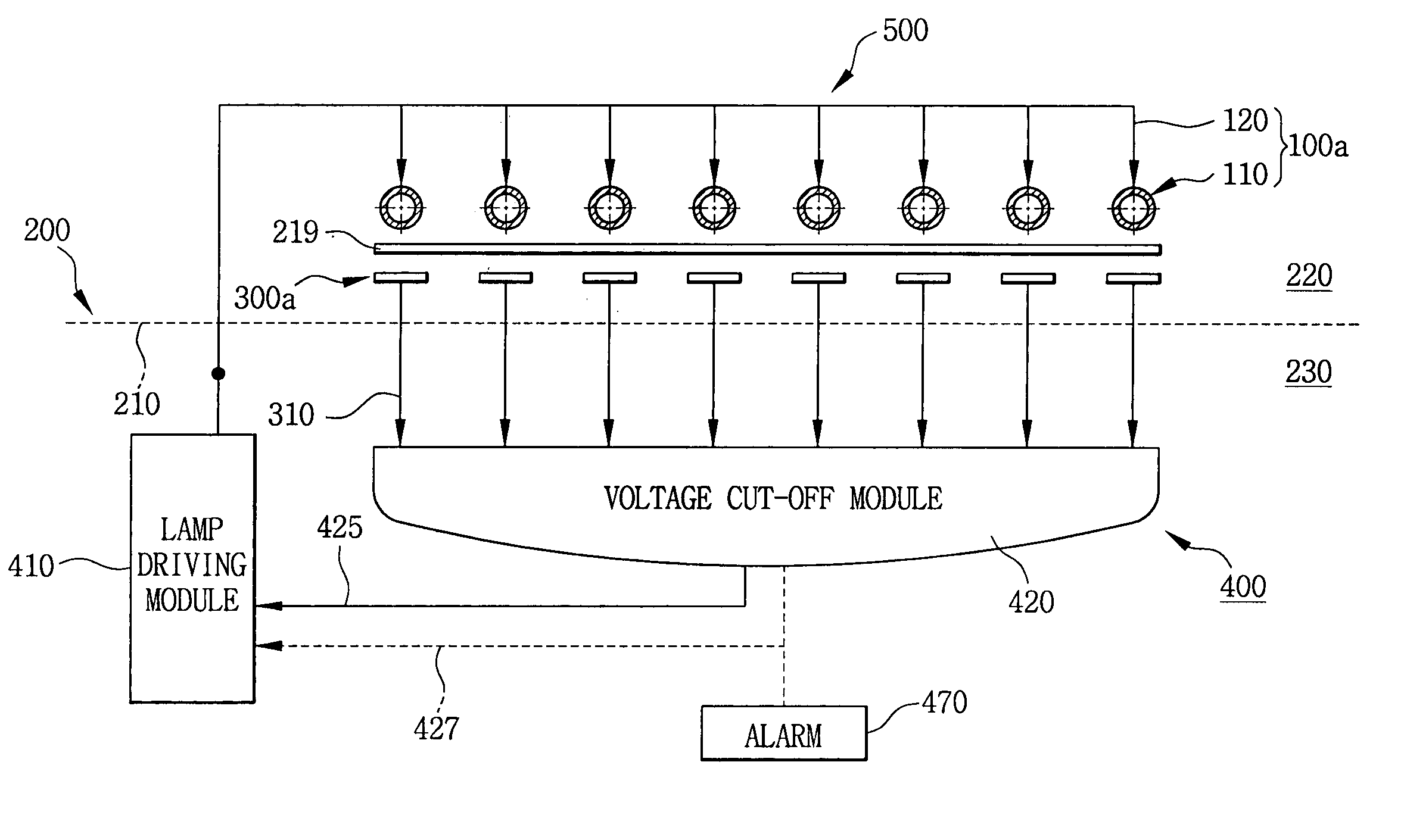
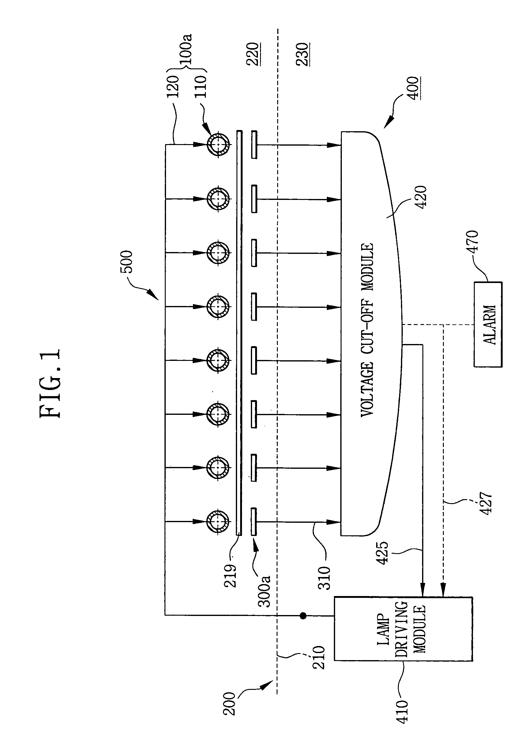
[0030]FIG. 1 is a schematic view showing a backlight assembly according to a first exemplary embodiment of the present invention. The backlight assembly according to the first exemplary embodiment of the present invention is employed in display device such as liquid crystal display device, display panel for displaying an advertisement message, projection television etc.

[0031]Referring to FIG. 1, the backlight assembly 500 includes a lamp assembly 100a, a receiving container 200, a plurality of sensors 300a and an inverter 400.

[0032]The lamp assembly 100a includes a plurality of lamps 110 and a module 120.

[0033]Each of the lamps 110 is arranged in parallel with each other. Each of the lamps 110 receives power voltage generated from the inverter 400 through the module 120, and generates light.

[0034]The lamps 110 are connected in parallel to the ...


PUM

PropertyMeasurementUnit
distanceaaaaaaaaaa
distanceaaaaaaaaaa
distanceaaaaaaaaaa

Abstract

In a backlight assembly and a liquid crystal display device using the backlight assembly, a lamp assembly is mounted on a receiving container and includes lamps. The lamps are connected in parallel and are turned on by the power voltage supplied from a lamp driving module. Sensors are disposed in the receiving container to face the lamps, and detect operation state of the lamps to output sensing signals. A voltage cut-off module is disposed outside of the receiving container, provides the lamp driving module with a voltage cut-off signal when at least one of the sensing signals has an amplitude smaller than a reference signal. The deterioration of the lamps may be prevented, and the life expectancy of lamps may be increased.

Description

CROSS-REFERENCE TO RELATED APPLICATIONS[0001]This application relies for priority upon Korean Patent Application No.2003-13182 filed on Mar. 3, 2003, the contents of which are herein incorporated by reference in its entirety.BACKGROUND OF THE INVENTION[0002]1. Field of the Invention[0003]The present invention relates to a backlight assembly and liquid crystal display device using the same.[0004]2. Description of the Related Art[0005]A liquid crystal display (LCD) device is a flat panel display device and display an image by means of liquid crystal. The liquid crystal changes a transmissivity of light passing through the liquid crystal according to an electric field applied to the liquid crystal.[0006]However, since the liquid crystal is not able to generate light, the liquid crystal display device employs lamps so as to display images under dark environment. The liquid crystal display device having a small screen size employs one or two lamps so as to display images.[0007]According ...

Claims


Application Information

Patent Timeline
Patent Type & Authority Patents(United States)
IPC IPC(8): G09G3/36F21S2/00F21S8/04F21Y103/00G02F1/133G02F1/13357G09G3/34H05B37/02H05B37/03H05B41/24H05B41/285
CPCG02F1/133604H05B41/2855H05B37/032G09G3/3406G02F2001/133612G09G2360/145H05B47/21G02F1/133612G02F1/133
Inventor KIM, MIN-GYUPARK, JONG-DAELEE, JEONG-HWANLEE, SANG-HOONHAN, BYUNG-WOONGKIM, HYOUNG-JOOKIM, DONG-HOON
Owner SAMSUNG DISPLAY CO LTD
Why Eureka
Try Eureka