Method of driving display apparatus and plasma display apparatus

a technology of display apparatus and plasma, which is applied in the direction of instruments, television systems, static indicating devices, etc., can solve the problems of affecting the quality of display, so as to improve the quality of display and reduce flicker.

Inactive Publication Date: 2006-10-24
FUJITSU HITACHI PLASMA DISPLAY LTD
View PDF23 Cites 9 Cited by
  • Summary
  • Abstract
  • Description
  • Claims
  • Application Information

AI Technical Summary

Benefits of technology

[0022]The present invention will solve the above-mentioned problems and the first object is to realize a driving method with less flicker even when the apparatus is driven at a frequency of 50 Hz and the second object is to realize a driving method employing the subfield method that improves many items relating to the image quality.
[0028]In the method of driving a display apparatus in the second aspect of the present invention, the rest period is divided into plural rest periods and the divided periods are arranged between plural different subfields. According to the second aspect of the present invention, when the rest period occurs, it is divided into plural periods and arranged in different positions between subfields, therefore, flicker does not increase if the rest period is provided or the rest period is lengthened because the changes in position of the light emission period of each subfield are small and the increase of the component of a low frequency of the variation of the light emission intensity can be reduced.
[0032]According to the third aspect of the present invention, since the original clock frequency is varied, it is possible to vary the number of pulses to be lit without changing the address period and the light period of each subfield and to maintain the relation among the light periods of each subfield constant.

Problems solved by technology

When the gradation scale is attained by the subfield method in a display apparatus of “address / sustain period separated type-write address method”, the sustain periods where light emission takes place are separate from each other because an address period exists in each subfield, and a problem of the degradation of display quality such as flicker and color false contour is caused depending on the displayed image, because the lengths of the sustain periods are not equal.
This art, however, cannot provide a sufficient quality of display.
It was found that flicker is not a problem when the arts disclosed in the above-mentioned Japanese Unexamined Patent Publication (Kokai) No. 3-145691 and Japanese Unexamined Patent Publication (Kokai) No. 7-271325 are applied to the plasma display apparatus using the NTSC method to improve the quality of image, but in the case of the plasma display apparatus using the PAL method, flicker remains a problem even when the above-mentioned arts are applied.
As described above, the plasma display apparatus that operates at a frequency of 50 Hz generates a strong flicker and thus a problem in the image quality occurs.
For example, when driven at a frequency of 50 Hz, a problem in that the intervals between the sustain periods of each subfield are narrowed, the frequency component of 50 Hz is increased and the image quality is degraded, is caused.
Among various items that relate to the image quality, the above-mentioned flicker and the degradation of the contour in animation are problems relating to the subfield method.
The problem of the degradation of the contour in animation, for example, results in the color false contour, in which the contour of a moving part is colored, when animation is shown on the color display apparatus.
The art disclosed in Japanese Unexamined Patent Publication No. 7-271325 suppresses the occurrence of color false contour, but if a plasma display apparatus to which this art is applied is driven at a frequency of 50 Hz, the problem of flicker occurs.
It is thus found impossible to improve every item relating to the image quality with a limited number of subfields.

Method used


Image

  • Method of driving display apparatus and plasma display apparatus
  • Method of driving display apparatus and plasma display apparatus
  • Method of driving display apparatus and plasma display apparatus

Examples


first embodiment

[0056]FIG. 9A and FIG. 9B are diagrams that show the frame structure and the variation of the light emission intensity of the method of driving the plasma display apparatus in the present invention.

[0057]As shown in FIG. 9A, in the frame structure in the first embodiment, a total of 10 subfields, that is, subfields of 24, 16, 8, and 4 brightness weight in pairs, respectively, and subfields of 2 and 1 brightness weight each, are provided and arranged in order of brightness weight of 24, 8, 4, 16, 1, 2, 24, 8, 4, and 16. In this example, the rest period is arranged at the end of the frame, the sustain period of the subfield of 24 brightness weight is arranged so that the interval of the sustain period is about half the length of the frame plus the rest period, and the two subfields of 16 brightness weight are arranged at the interval of about half the length of the frame so that each of them is arranged almost at the midpoint between the two subfields of 24 brightness weight. When the...

third embodiment

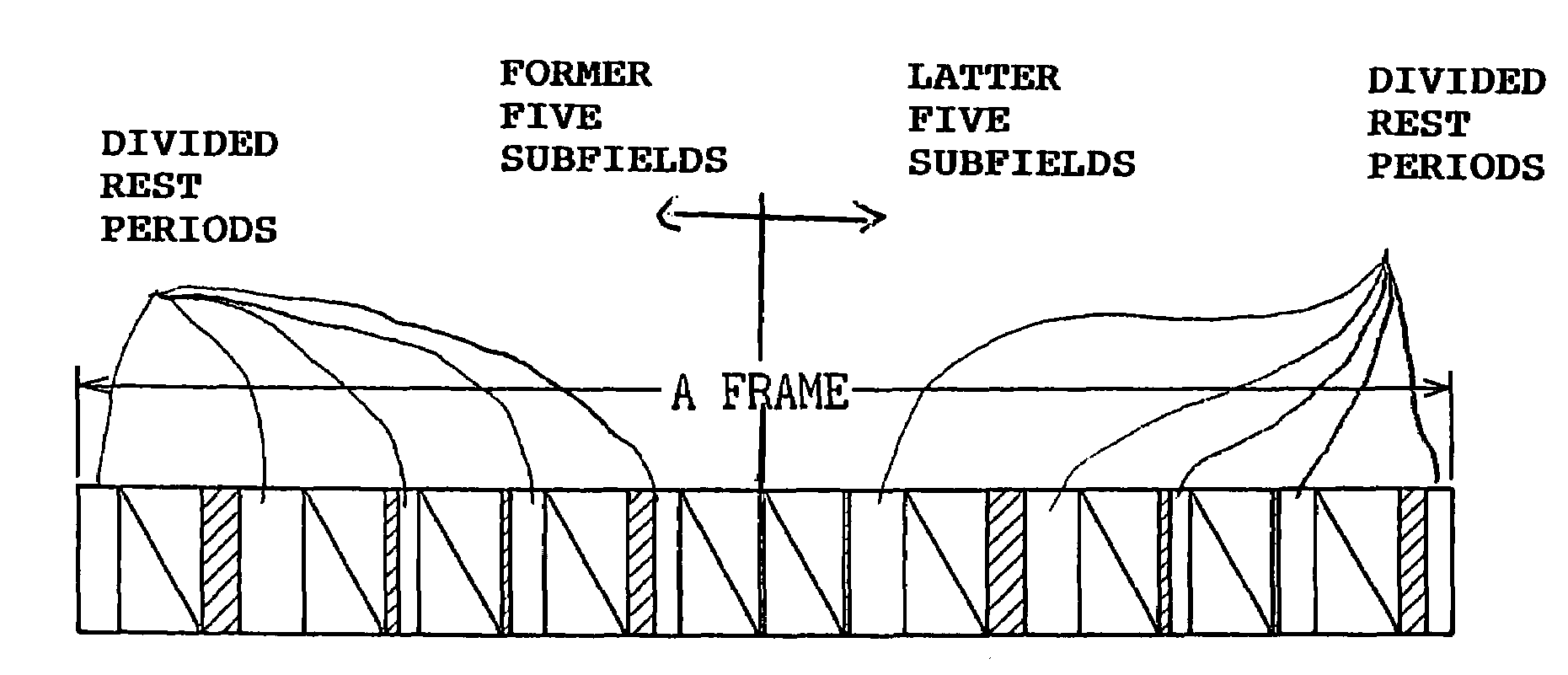
[0062]In the frame structure in the third embodiment, a total of 10 subfields, that is, subfields of 24, 16, 8, and 4 brightness weight in pairs, respectively, and subfields of 2 and 1 brightness weight each, respectively, are provided and after subfields of 24, 8, 4, 16, 1, and 2 brightness weight are arranged in this order, the first rest period is provided, and then subfields of 24, 8, 4, and 16 brightness weight are arranged in this order and finally, the second rest period is provided. In other words, the rest period is divided into two and arranged between subfields apart from each other. The two subfields of 24 brightness weight are arranged after the rest period (before the previous subfield of 24 brightness weight, there exists the rest period of the previous frame), and when the length of the rest period varies, the lengths of the first and the second rest periods are varied so that the positions of the sustain periods of the two subfields of 24 brightness weight do not ch...

sixth embodiment

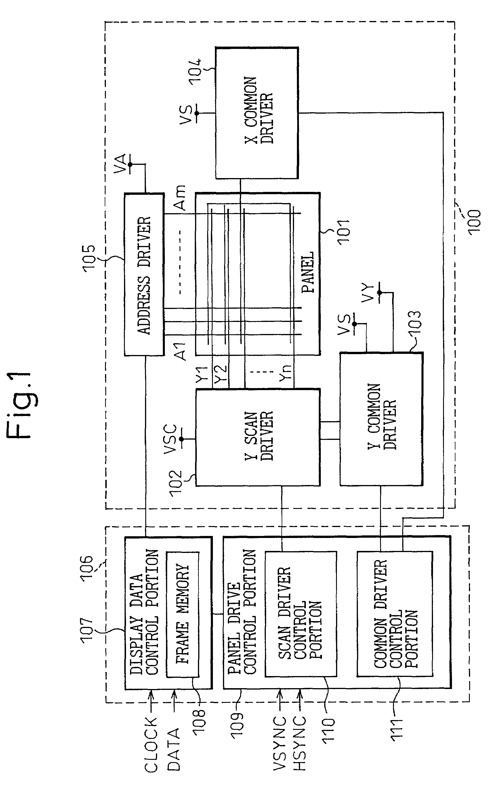
[0071]In order to realize the driving method in the sixth embodiment, the panel drive control portion 109 in the drive circuit of the PDP apparatus in FIG. 1 is made to have a structure as shown in FIG. 16 so that the period of the sustain pulse can be varied. In the panel drive control portion 109, a CPU 121 controls the number of sustain pulses of each subfield according to the brightness adjust signal entered from the outside, the internal power control, and so on. The sustain period of each subfield is constant and the CPU 121 determines the period (frequency) of the sustain pulse based on the number of sustain pulses of each subfield and the length of the sustain period, generates the corresponding control data, and puts out to a D / A converter 122. The D / A converter 122 generates analog signals corresponding to the control data and applies it to a VCO 123. The VCO 123 generates clocks of a frequency corresponding to these analog signals (termed “an original clock freguency”), a...


PUM


Abstract

The method of driving a display apparatus, in which the gradation scale is represented, by the subfield method, with less flicker even when driven at a frequency of 50 Hz has been disclosed. In this method, the two most weighted subfields (subfields of Bn brightness and Bn−1 brightness when it is assumed that the frame is composed of n subfields and the brightness of n subfields is Bi (i=1−n; B1≦B2 . . . Bn−1≦Bn)) are arranged at the interval of about half the length of the frame. Because of this, there exist two peaks of the light emission intensity in a frame, the interval being about half the length of the frame, and if the display apparatus is driven at a frequency of 50 Hz and the length of the frame is 20 ms, the variation period of the light emission intensity is 10 ms and the light emission intensity varies at 100 Hz, therefore, flicker is not detected.

Description

BACKGROUND OF THE INVENTION[0001]The present invention relates to a method of driving a display apparatus in which the gradation scale is represented by a subfield structure. More particularly, the present invention relates to a method of driving a display apparatus such as a plasma display in which each subfield has at least an address period and a light period.[0002]Description is made below with an example of a plasma display (simply referred to as a PDP hereinafter). The present invention, however, is not limited to a PDP but applicable to any type of display apparatus as long as the gradation scale is represented by a subfield structure and each subfield has at least an address period and a light period.[0003]Since information about a PDP has been disclosed in, for example, Japanese Unexamined Patent Publication (Kokai) No. 7-271325, a detailed description is omitted here and only an outline of the structure and the driving method is given.[0004]FIG. 1 is a block diagram that s...

Claims


Application Information

Patent Timeline
Patent Type & Authority Patents(United States)
IPC IPC(8): G09G5/10G09G3/10G09G5/00H04N5/14H04N5/66G09G3/20G09G3/28G09G3/291G09G3/294G09G3/296G09G3/298
CPCG09G3/2029G09G3/2803G09G3/2944G09G3/204G09G2320/0247G09G2320/0266G09G3/296
Inventor YAMAMOTO, AKIRAKURIYAMA, HIROHITOKOJIMA, AYAHITOTODA, KOSAKU
Owner FUJITSU HITACHI PLASMA DISPLAY LTD
Why Eureka
Try Eureka