
Memory efficient LDPC decoding methods and apparatus

a ldpc decoder and memory-efficient technology, applied in the direction of coding, instruments, code conversion, etc., can solve the problems of inability to meet one or more real-world decoding time constraints, inability to implement information transfer, and bits might be punctured, so as to avoid significant delays and/or reduce delays in memory-efficient ldpc decoders.

Active Publication Date: 2006-10-24
QUALCOMM INC
View PDF39 Cites 66 Cited by
  • Summary
  • Abstract
  • Description
  • Claims
  • Application Information

AI Technical Summary

Benefits of technology

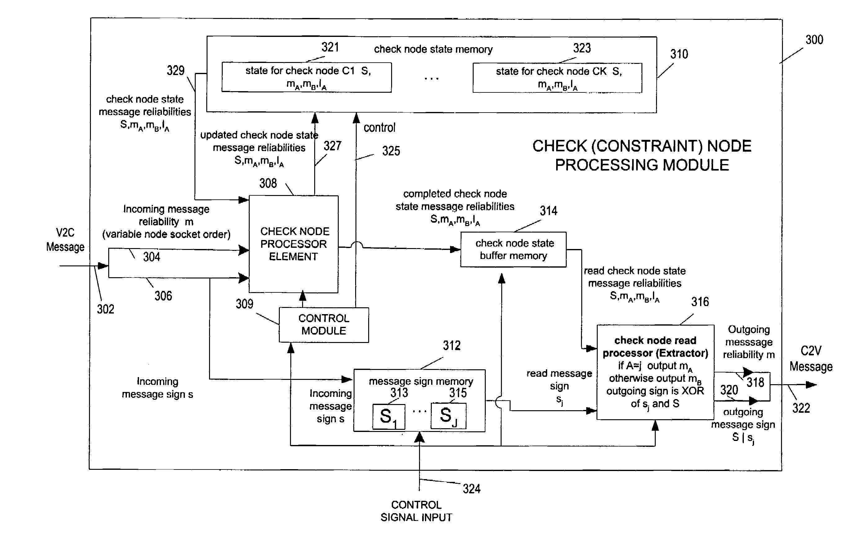
The present invention is about methods and apparatus for efficiently performing LDPC decoding operations in a memory-efficient manner. The invention uses check node processing techniques that compress and decompress message information to reduce storage requirements and processing delays. The invention also avoids introducing significant delays in the decoding process by using LDPC codes with a structure that avoids introducing significant delays. The invention also includes a method for generating check node output messages without having to process messages from variable nodes that will be processed much later during the decoding process. The invention reduces timing delays associated with check node output message generation and minimizes the impact of variable node messages on the decoding process.

Problems solved by technology

Error correcting codes compensate for the intrinsic unreliability of information transfer in these systems by introducing redundancy into the data stream.
In some cases some of these bits might be punctured.
While memory reduction is of a concern, in reducing the amount of memory used, it is often necessary to avoid a design which would impose unacceptable processing delays which might result in the failure to meet one or more real world decoding time constraints.

Method used


Image

  • Memory efficient LDPC decoding methods and apparatus
  • Memory efficient LDPC decoding methods and apparatus
  • Memory efficient LDPC decoding methods and apparatus

Examples


Embodiment Construction

[0050]The following (3) related applications are hereby expressly incorporated by reference and are to be considered part of the present application: U.S. patent application Ser. No. 09 / 975,331 filed Oct. 10, 2001 entitled “METHODS AND APPARATUS FOR DECODING LDPC CODES”, U.S. patent application Ser. No. 10 / 117,264 filed Apr. 4, 2002 entitled “NODE PROCESSORS FOR USE IN PARITY CHECK DECODERS”, and U.S. patent application Ser. No. 10 / 618,325 filed Jul. 11, 2003 entitled “METHODS AND APPARATUS FOR ENCODING LDPC CODES”.

[0051]Various embodiments of the present invention are directed to methods and apparatus which provide a simple, e.g., low hardware complexity, implementation of an LDPC decoder architecture. The methods and apparatus of the invention take advantage of the observation that, for certain algorithms, the reliabilities sent out from a check node take on one of two possible values and one of those values is sent along only one message edge. This is the case, for example, for t...


PUM


Abstract

Methods and apparatus for implementing memory efficient LDPC decodes are described. In accordance with the invention message information is stored in a compressed state for check node processing operations. The state for a check node is fully updated and then subject to an extraction process to generate check node to variable node messages. The signs of messages received from variable nodes may be stored by the check node processor module of the invention for use in message extraction. The check node processor can process messages in variable node order thereby allowing the variable node processor and check node processor to operate on messages in the same order reducing or eliminating the need to buffer and / or reorder messages passed between check nodes and variable nodes. Graph structures which allow check node processing on one graph iteration to proceed before the previous graph iteration has been completed are also described.

Description

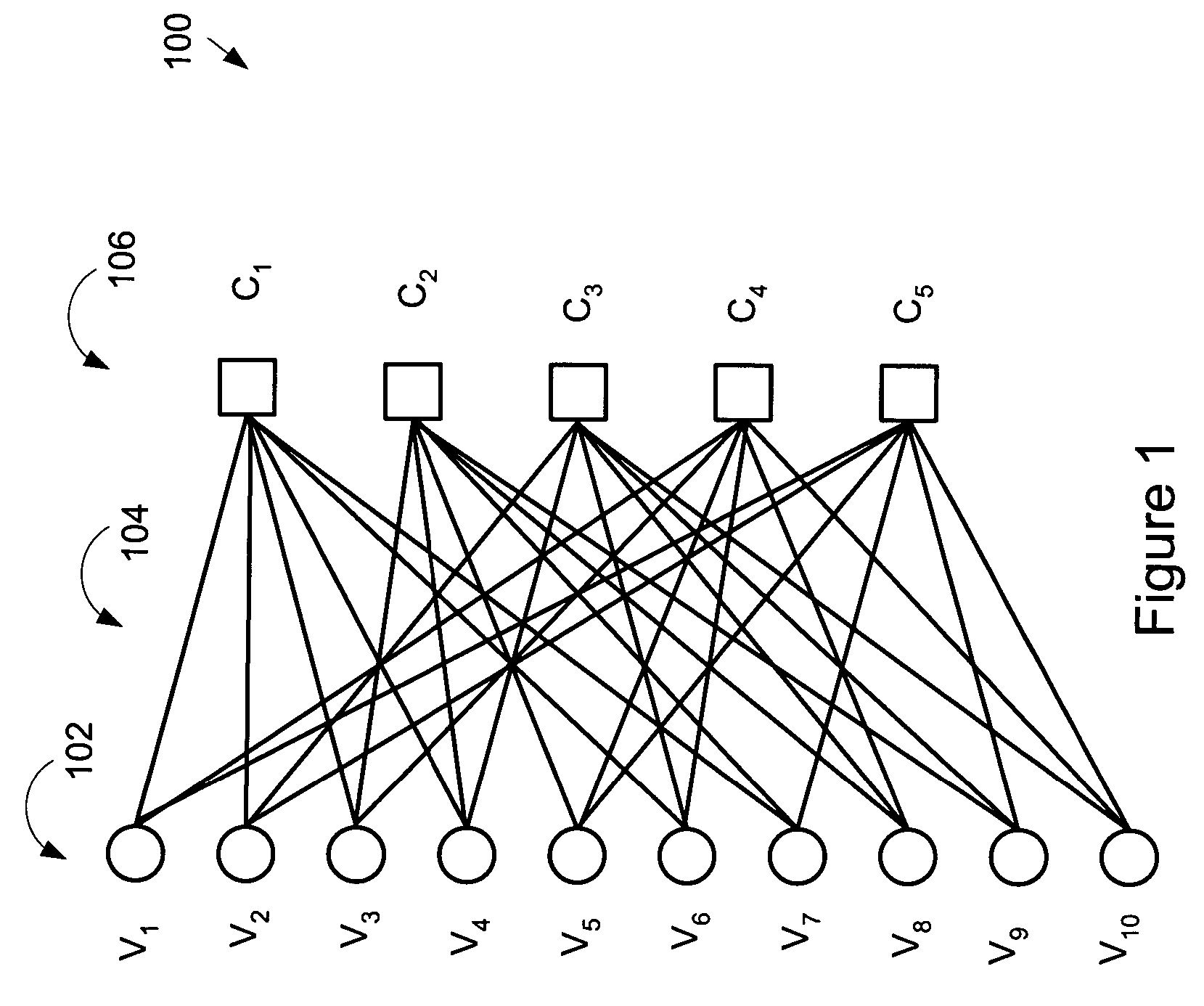
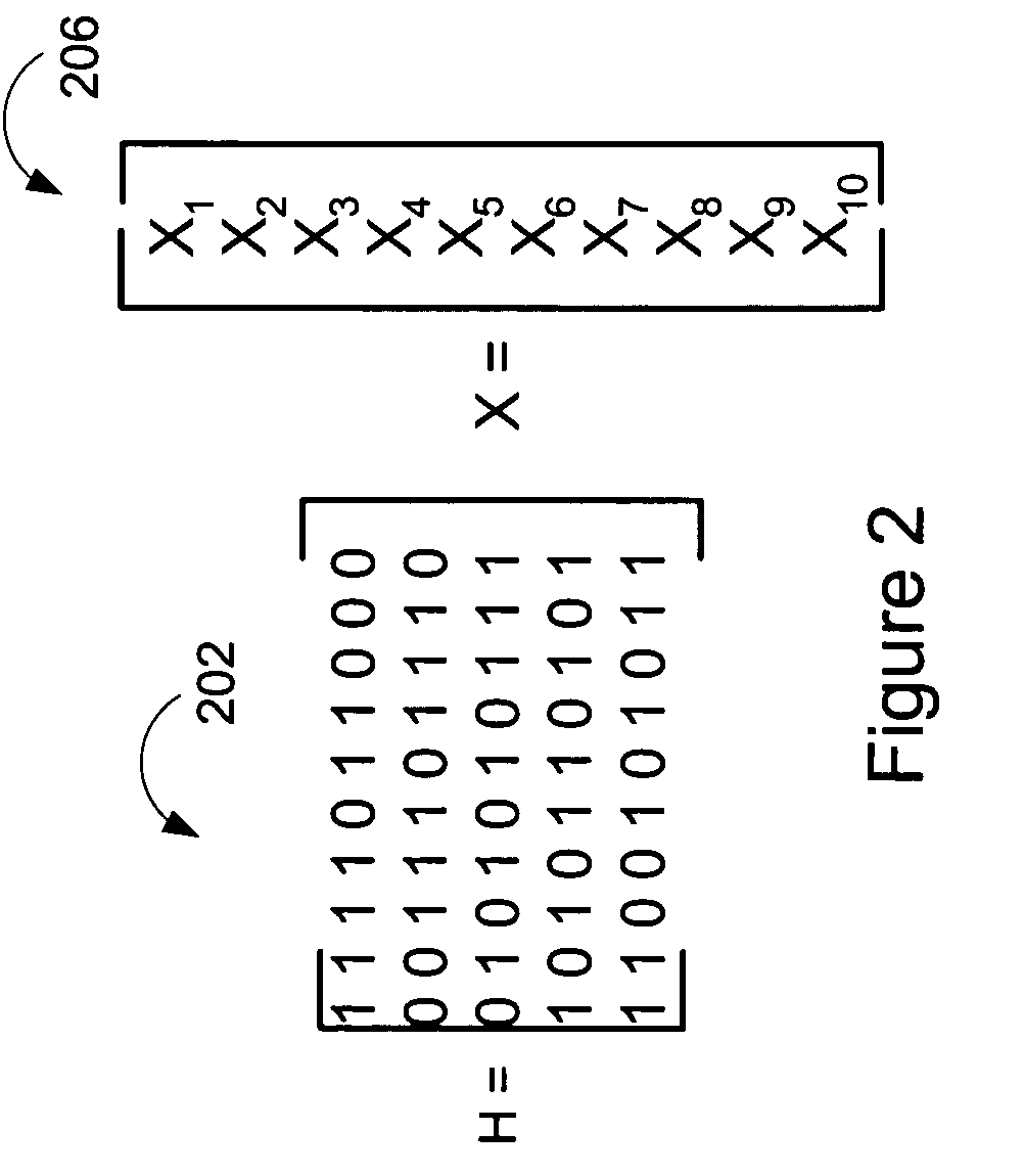
BACKGROUND OF THE INVENTION[0001]Nearly all forms of electronic communication and storage systems use error-correcting codes. Error correcting codes compensate for the intrinsic unreliability of information transfer in these systems by introducing redundancy into the data stream. The mathematical foundations of error correcting were established by Shannon. Shannon developed the mathematical concept of the channel in which distortion of signals in communications systems is modeled as a random process. The most fundamental result of Shannon is the Noisy channel theorem, which defines for the channel a capacity, a quantity that specifies the maximum rate at which information can be reliably delivered through the channel. Reliable transmission at rates approaching capacity requires the use of error correcting codes. Thus, error-correcting codes are designed to achieve sufficient reliability while approaching capacity as closely as possible. The complexity of implementing the error corre...

Claims


Application Information

Patent Timeline
Patent Type & Authority Patents(United States)
IPC IPC(8): H03M13/00
CPCH03M13/1105H03M13/1111H03M13/1117H03M13/1122H03M13/1137H03M13/6362H03M13/1114H03M13/11H03M13/00
Inventor RICHARDSON, TOMNOVICHKOV, VLADIMIR
Owner QUALCOMM INC
Learn More