Cable tie

a cable tie and a technology of abutment wall, applied in the direction of hose connection, flexible element, packaging, etc., can solve the problems of ratchet teeth being released from the pawl, product would be extremely difficult to manufacture, etc., and achieve the effect of short mold residence time and increased rigidity of the abutment wall

Active Publication Date: 2006-10-31
ADVANCED CABLE TIES
View PDF10 Cites 16 Cited by
  • Summary
  • Abstract
  • Description
  • Claims
  • Application Information

AI Technical Summary

Benefits of technology

[0006]It is therefore an object of this invention to provide a cable tie with increased rigidity of the abutment wall while maintaining a relatively short mold residence time.
[0007]This invention features a cable tie comprising an elongated tongue with two ends and two broad sides, a tip at one end of the tongue, a set of ratchet teeth extending along one broad side of the tongue, a locking head at the other end of the tongue, the locking head having sides defining an opening for receiving the tip of the tongue, and a movable pawl that is hinged at one side of the opening, with another side of the opening defining an abutment wall that is across the opening from the pawl, and wherein the pawl engages with one or more of the ratchet teeth when the tongue has been inserted through the opening with the set of ratchet teeth facing the pawl. The abutment wall defines at least one protruding cross member, to strengthen the abutment wall.
[0011]Featured in another embodiment is a cable tie comprising an elongated tongue with two ends and two broad sides, a tip at one end of the tongue, a set of ratchet teeth extending along one broad side of the tongue, and a locking head at the other end of the tongue. The locking head has sides defining an opening for receiving the tip of the tongue, and a movable pawl that is hinged at one side of the opening, with another side of the opening defining an abutment wall that is across the opening from the pawl. The pawl engages with one or more of the ratchet teeth when the tongue has been inserted through the opening with the set of ratchet teeth facing the pawl. The abutment wall defines at least a pair of protruding longitudinal cross members that extend in total along at least a substantial portion of the length of the abutment wall in the direction of insertion of the tip of the tongue in the opening in the locking head, and at least one essentially perpendicular cross member that intersects the longitudinal cross members, to strengthen the abutment wall.

Problems solved by technology

If sufficient force is applied, the abutment wall can bow outward, which can cause the ratchet teeth to release from the pawl.
However, this product would be extremely difficult to manufacture.

Method used


Image

  • Cable tie
  • Cable tie
  • Cable tie

Examples


Embodiment Construction

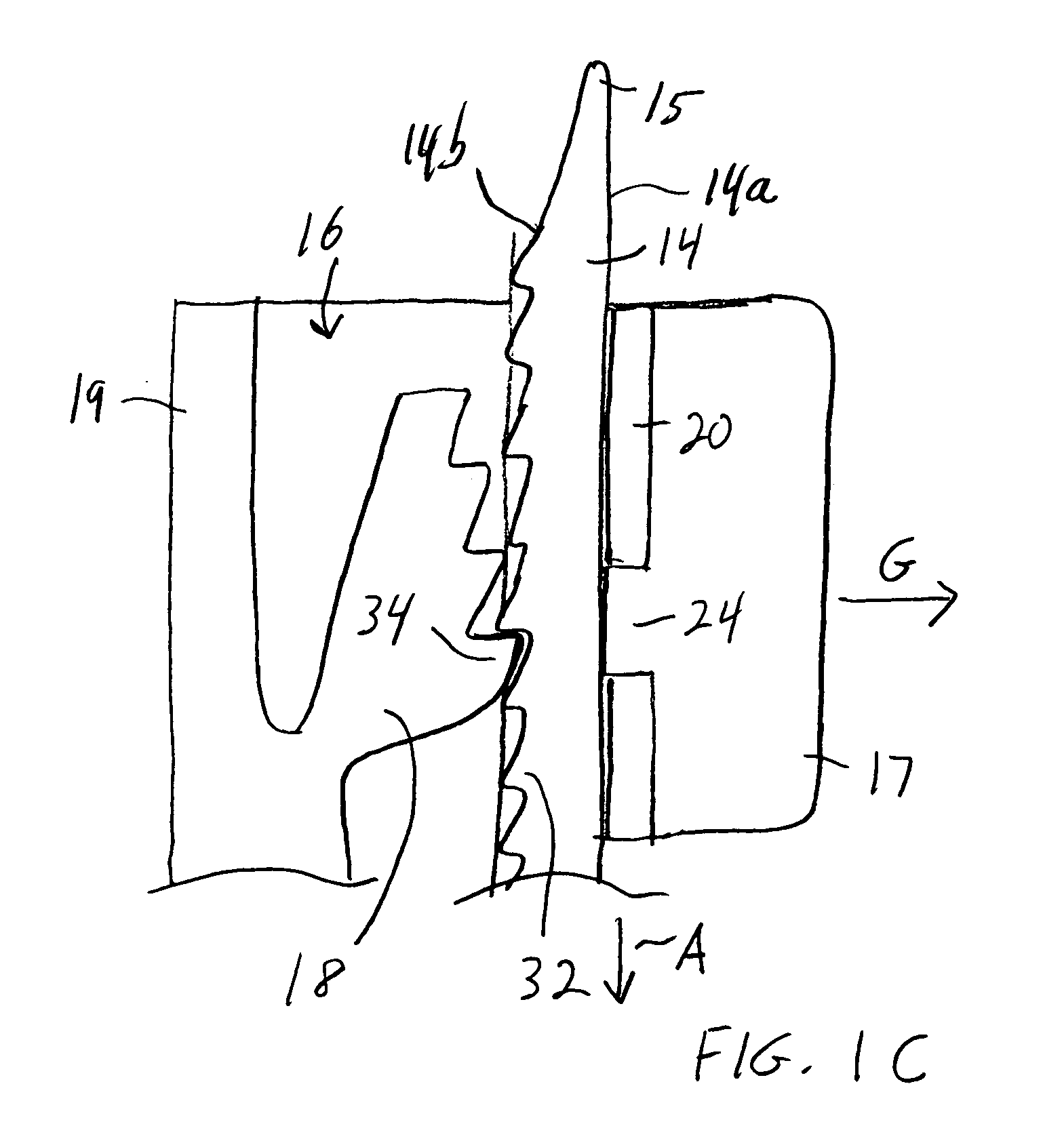
[0020]The invention may be accomplished in a cable tie in which the abutment wall of the cable tie head is reinforced with at least two transverse cross members located on one or both surfaces of the abutment wall. The cross members reinforce the wall to inhibit its buckling under substantial loads, while maintaining a profile that does not substantially increase the residence time required in the mold to solidify the abutment wall.

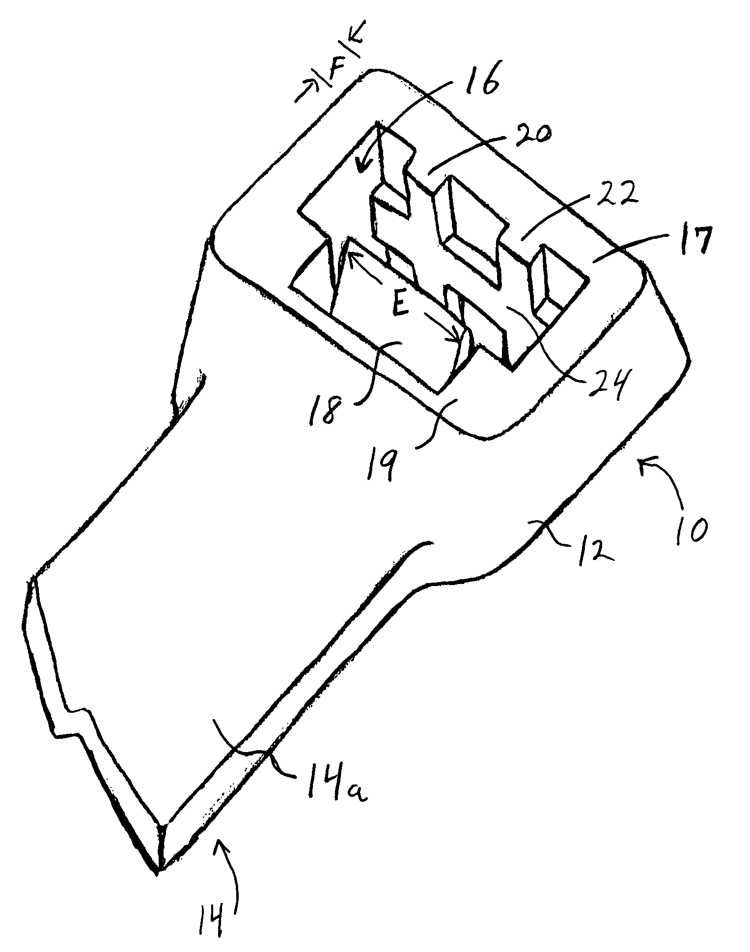
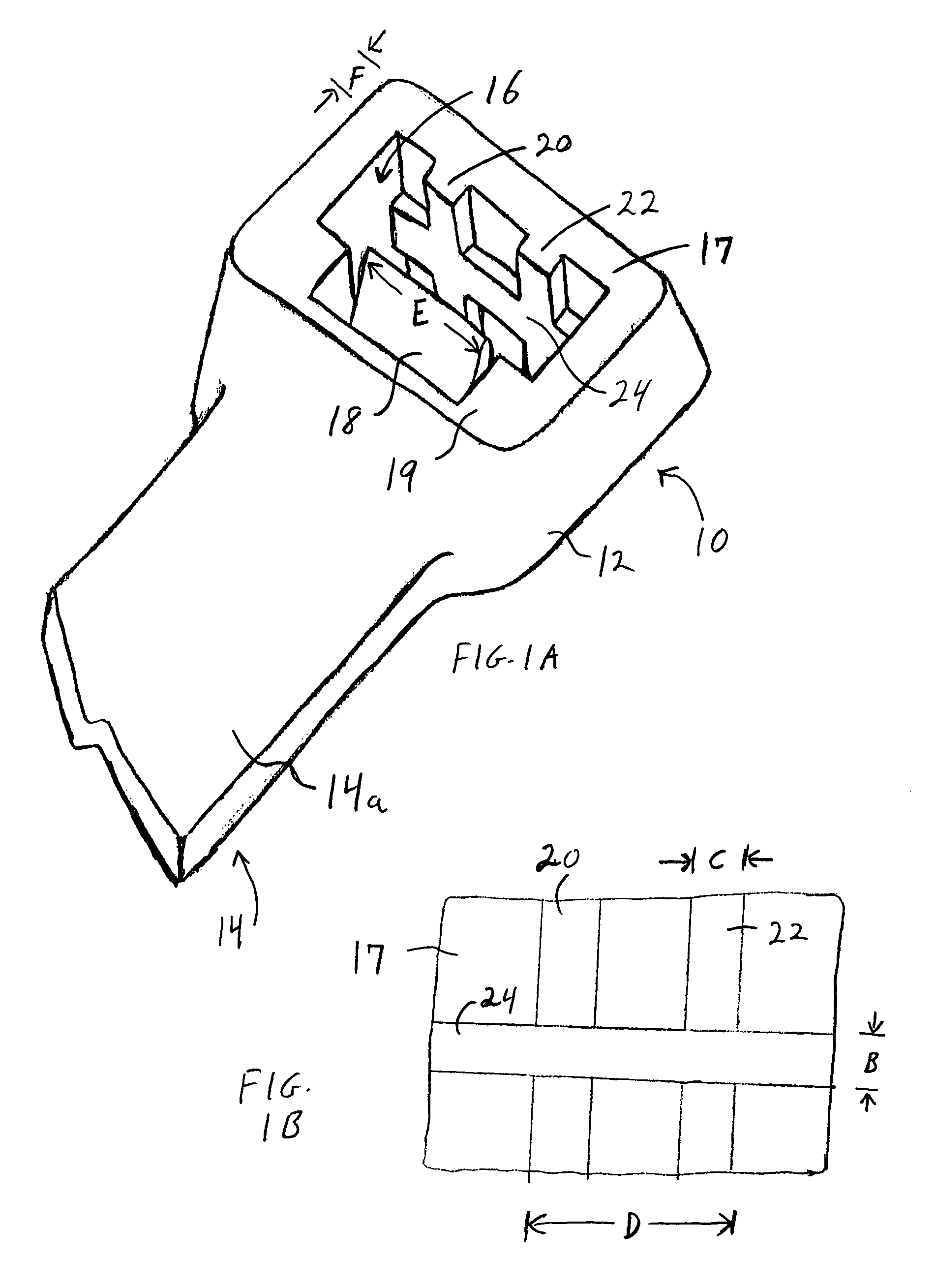
[0021]FIGS. 1A–1C depict a preferred embodiment of the inventive cable tie. Cable tie 10 comprises elongated tongue 14 with broad upper side 14a and broad lower side 14b. Head 12 is located at one end of tongue 14, and tip 15 at the other end. Locking head 12 defines opening 16 for receiving tip 15 of tongue 14. Integral moveable pawl 18 is hinged at side 19 of head 12. Across opening 16 from pawl 18 is abutment wall 17. Wall 17 is strengthened by the inclusion of at least one protruding cross member. Although the cross member or cross members can be loca...


PUM


Abstract

A cable tie with an elongated tongue with two ends and two broad sides, a tip at one end of the tongue, a set of ratchet teeth extending along one broad side of the tongue, and a locking head at the other end of the tongue, the locking head having sides defining an opening for receiving the tip of the tongue, and a movable pawl that is hinged at one side of the opening, with another side of the opening defining an abutment wall that is across the opening from the pawl. The pawl engages with one or more of the ratchet teeth when the tongue has been inserted through the opening with the set of ratchet teeth facing the pawl. The abutment wall defines at least one protruding cross member, to strengthen the abutment wall.

Description

FIELD OF THE INVENTION[0001]This invention relates to a cable tie.BACKGROUND OF THE INVENTION[0002]Cable ties are useful for quickly and securely retaining together two or more items, for example the conductors in a wiring harness. Several examples of cable ties are shown in U.S. Pat. Nos. 5,263,231; 5,440,786; and 5,615,455. In a general sense, a cable tie is an elongated tongue with a tip at one end and a locking head at the other end. A set of ratchet teeth are located on the underside of the tongue. The locking head has an integral movable pawl that is hinged at one side of an opening in the locking head. When the tip is inserted in the opening and pulled through the head, the pawl engages with the ratchet teeth to prevent the tip from being pulled back out of the opening.[0003]When force is applied to an engaged cable tie, the tongue is pulled in a direction opposite to that in which it was inserted in the head. This causes the pawl to be pulled farther away from its attachment...

Claims


Application Information

Patent Timeline
Patent Type & Authority Patents(United States)
IPC IPC(8): B65D63/00
CPCB65D63/1072Y10T24/1498Y10T24/141
Inventor HEWES, DAVID A.
Owner ADVANCED CABLE TIES
Why Eureka
Try Eureka