Gravel pack crossover tool with single position multi-function capability

a multi-functional, cross-over technology, applied in the direction of fluid removal, sealing/packing, borehole/well accessories, etc., can solve the problems of difficulty in finding the intermediate position for reversing the gravel out from below the packer b>14/b> from the surface, and the liquid column above the packer can no longer exert pressure on the formation

Active Publication Date: 2006-10-31
BAKER HUGHES INC
View PDF24 Cites 100 Cited by
  • Summary
  • Abstract
  • Description
  • Claims
  • Application Information

AI Technical Summary

Benefits of technology

[0008]A gravel packing method and apparatus are described where to set the packer; a ball is dropped to a seat that it isolated from the effects of formation pressures when trying to set the packer. This is accomplished by isolation of the gravel pack outlet port when setting the packer and locating the ball seat in a position where the effects of formation pressure are irrelevant. Additionally, by positioning the evacuation ports above a seal bore in the screen extension during circulation to deposit gravel and further putting check valves in the evacuation ports, the evacuation step after circulation can be accomplished without having to reposition the crossover. The crossover tool is supported from the packer and movement of the crossover tool away and back to the support from the packer operates a valve to allow squeezing when the valve is closed and circulating and reversing out when the valve is open.

Problems solved by technology

One of the problems with this layout is that if the formation is under sub-hydrostatic pressure, such sub-hydrostatic pressure communicates with the underside of ball 46 on seat 16 and limits the amount of pressure that can be applied from above, shown schematically as arrows 50, before breaking a shear pin on the ball seat 16.
Yet another drawback of this arrangement is that when the packer 14 makes contact with the wellbore 10 and the passage through its seal bore 38 is obstructed, the liquid column above the packer 14 can no longer exert pressure on the formation.
This can result in portions of the formation breaking off into the wellbore and potentially obstructing it.
The problem here is that the intermediate position for reversing gravel out from below the packer 14 is difficult to find from the surface.

Method used


Image

  • Gravel pack crossover tool with single position multi-function capability
  • Gravel pack crossover tool with single position multi-function capability
  • Gravel pack crossover tool with single position multi-function capability

Examples


Embodiment Construction

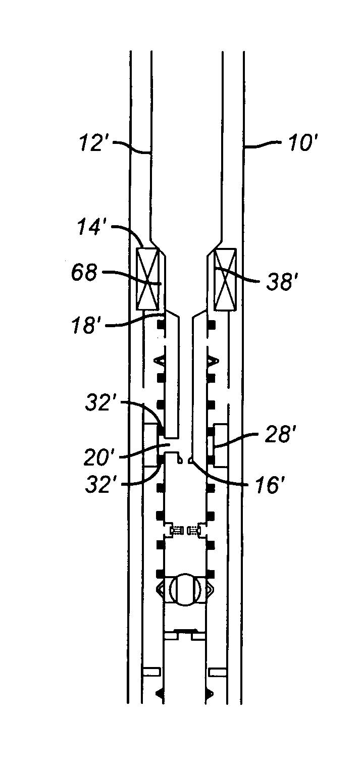
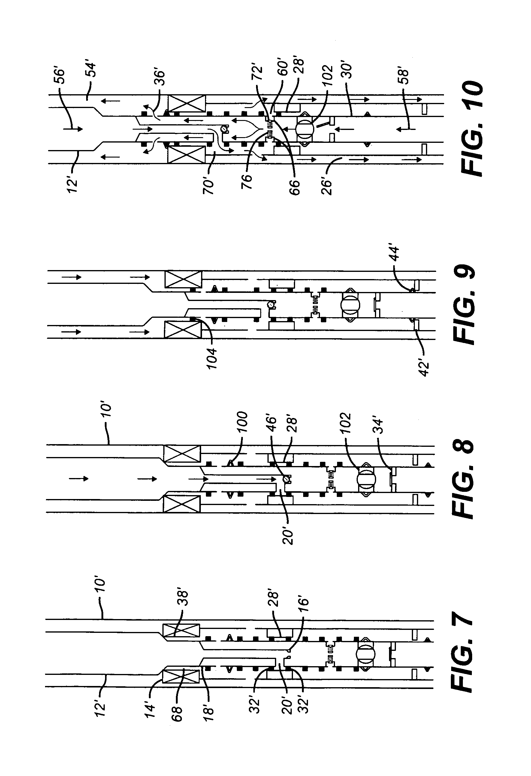
[0022]In the run in position of FIG. 7, the seal bore 38′ has a clearance 68 around the crossover tool 18′. The ball seat 16′ is located below gravel pack port 20′. During run in and setting of the packer 14′, the gravel pack port 20′ is sealed in seal bore 28′ by virtue of seals 32′. As shown in FIG. 8, when the ball 46′ lands on seat 16′ it will not go any lower. Thus exposure to sub-hydrostatic formation pressures below ball 46′ will not affect the setting of packer 14′. This is because there is no longer any need to shear out the seat 16′ due to its location below gravel pack port 20′. An upward shift of the crossover tool 18′ will position gravel pack port 20′ out and above seal bore 28′, as illustrated in FIG. 10, so that gravel slurry 56′ can be pumped down string 12′ and into annulus 26′ with returns 58′ coming through flapper 34′ and into annulus 54′ by way of return ports 36′. It should be noted that during circulation, the evacuation ports 60′ are above the seal bore 28′ ...


PUM


Abstract

A gravel packing method and apparatus allows setting the packer by dropping a ball to a seat that it isolated from the effects of formation pressures when trying to set the packer. This is accomplished by isolation of the gravel pack outlet port when setting the packer and locating the ball seat in a position where the effects of formation pressure are irrelevant. Additionally, by positioning the evacuation ports above a seal bore in the screen extension during circulation or squeeze to deposit gravel and further putting check valves in the evacuation ports, the evacuation step after circulation or squeeze can be accomplished without having to reposition the crossover. The crossover is supported from the packer and movement of the crossover away and back to the support from the packer operates a valve to allow squeezing when the valve is closed and circulating and reversing out when the valve is open. Thus, the gravel pack method and apparatus facilitates circulation, squeeze and reverse circulation in a single supported position.

Description

FIELD OF THE INVENTION[0001]The field of this invention is crossover tools for gravel packing a screen downhole and more particularly to crossover tools that permit the squeezing, circulating and reversing out with the tool in the same position with respect to a downhole packer.BACKGROUND OF THE INVENTION[0002]FIGS. 1–6 illustrate the prior art crossover tool in a typical gravel packing operation. The wellbore 10 receives a running string and setting tool shown schematically as 12. A packer 14 sealingly accepts the string and setting tool 12. A ball seat 16 is located in the crossover tool 18 just above gravel pack port 20. Screen extension 22 is attached to packer 14 and has ports 24 to permit gravel access to annulus 26. Screen extension 22 has a seal bore 28 through which a wash pipe 30 extends in sealing contact for run in, shown in FIG. 1, due to contact of seals 32. A flapper 34 allows uphole flow in wash pipe 30 and prevents downhole flow. Return ports 36 are in the seal bore...

Claims


Application Information

Patent Timeline
Patent Type & Authority Patents(United States)
IPC IPC(8): E21B43/04E21B34/14
CPCE21B34/14E21B43/045E21B43/04E21B34/12
Inventor CORBETT, THOMAS G.
Owner BAKER HUGHES INC
Why Eureka
Try Eureka