Method of making a proximity probe

a proximity probe and probe body technology, applied in the field of making proximity probes, can solve the problems of difficult replacement, deterioration of the probe, and the need for precision operation of the proximity probe, and achieve the effect of eliminating costly machining of the internal thread

Inactive Publication Date: 2003-11-11
BENTLY NEVADA INC
View PDF64 Cites 18 Cited by
  • Summary
  • Abstract
  • Description
  • Claims
  • Application Information

AI Technical Summary

Benefits of technology

Another further object of the present invention is to provide the proximity probe manufacturing method which includes eliminating both axially retractable and radially retractable support pins that respectively provide localized support at the front and sides of a coil and preform assembly and replacing all of these retractable support pins with a single support pin received within an opened interior of the preform along a longitudinal axis and via an opened rearward end distal from the sensing coil disposed at a forward most end of the preform.
Still yet another further object of the present invention is to provide a proximity probe and a proximity probe manufacturing method which eliminates costly machining of internal threads into a metal case which typically circumscribes the encapsulation of the encapsulated proximity probe tip by providing a metal casing having a geometrical opening within the metal casing, placing the metal casing on the encapsulated proximity probe tip, linearly positioning the metal casing on the encapsulated proximity probe tip at a location relative to the coil and heating the encapsulation proximate the geometrical opening such that a melted portion of the encapsulation is displaced into the geometrical opening for interlocking the metal casing to the encapsulation at the linearly positioned location.

Problems solved by technology

In general, proximity probes are required to operate with precision under very adverse physical, chemical, and mechanical conditions and are often difficult to replace.
Heretofore, both the epoxying process and the injection molding process used to cover the sensing coil have been known to leave seams or interruptions that are susceptible to, inter alia, predations of the environment such as fluid and / or vapor ingress (e.g., oil, oil vapor, water, and / or water vapor) into the interior of the probe thereby causing probe deterioration leading to, inter alia, inaccurate and unreliable probe measurements.
For example, the pins employed in the radial and axial pin pulling process have been known to cause areas that fail to be filled in with moldable material during the encapsulation process such that an opening, slit, or the like is formed that allows fluid and / or vapor ingress into the interior of the probe thereby causing probe deterioration leading to, inter alia, inaccurate and unreliable probe measurements.
Furthermore, the radial and axial pin pulling processes are problematic in that the sensing coil, preform and fixed cable length assembly may become misaligned within the encapsulation thereby altering the desired spacing between a target object and the sensing coil of the probe such that inaccurate and unreliable measurements are obtained when in operation.
Thus, if the coil becomes skewed within the encapsulation the displacement motion or position between the target object and one area of the skewed coil will be different than the displacement motion or position between the target object and another area of the skewed coil thereby providing erroneous and undependable probe measurements when in operation.
In fact, if the coil becomes skewed within the encapsulation the displacement motion or position between the target object and the sensing coil may completely fall out of the linear range of the proximity probe resulting in flawed probe measurements when in operation.

Method used


Image

  • Method of making a proximity probe
  • Method of making a proximity probe
  • Method of making a proximity probe

Examples


Embodiment Construction

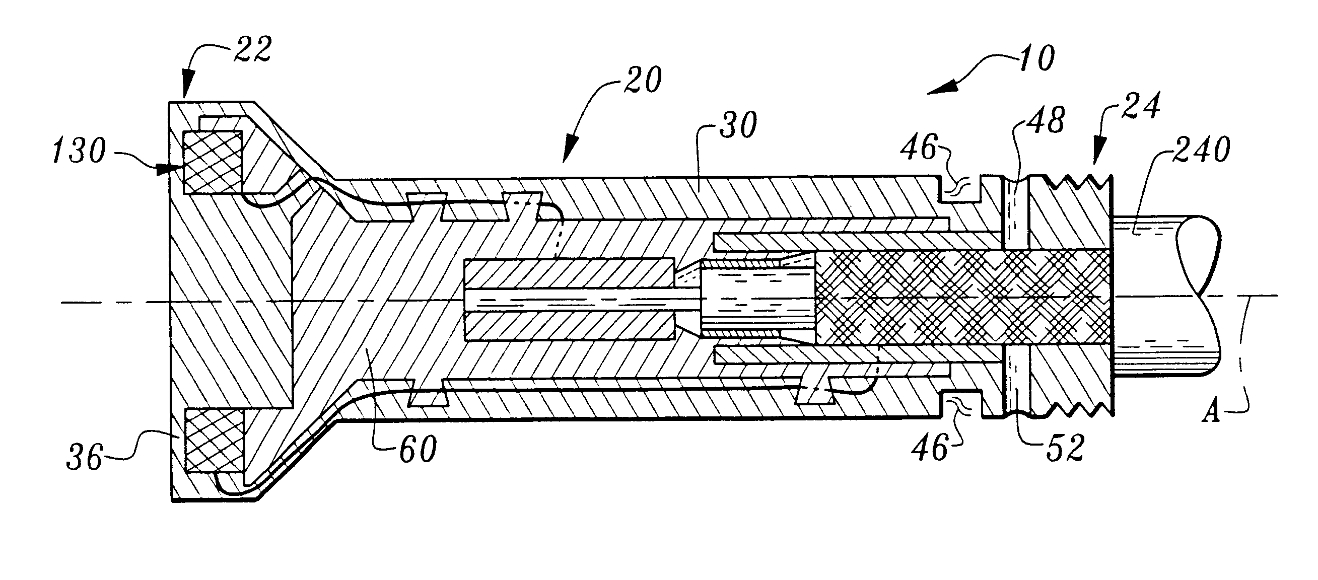
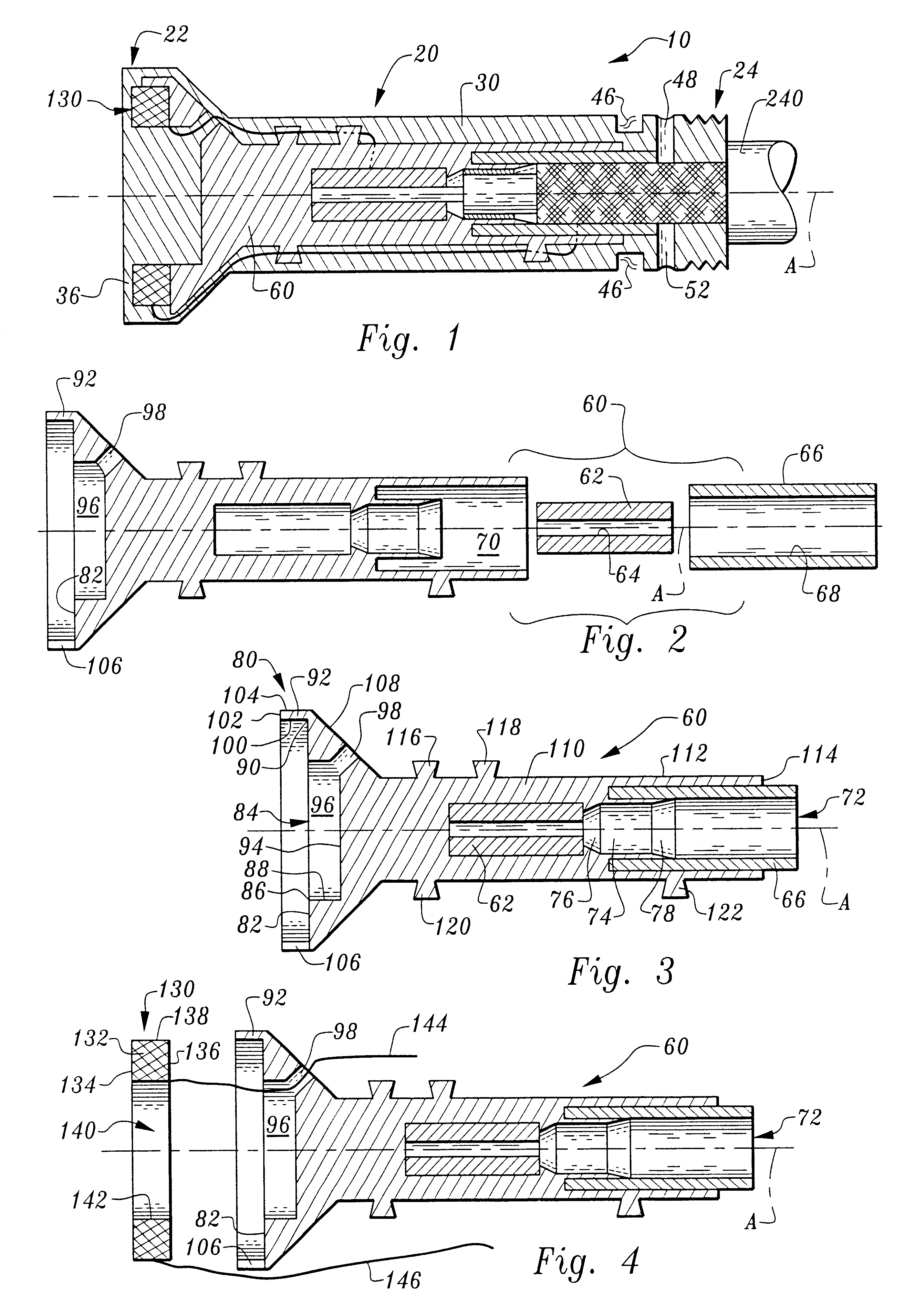
Considering the drawings, wherein like reference numerals denote like parts throughout the various drawing figures, reference numeral 10 is directed to the encapsulated proximity probe pursuant to the present invention.

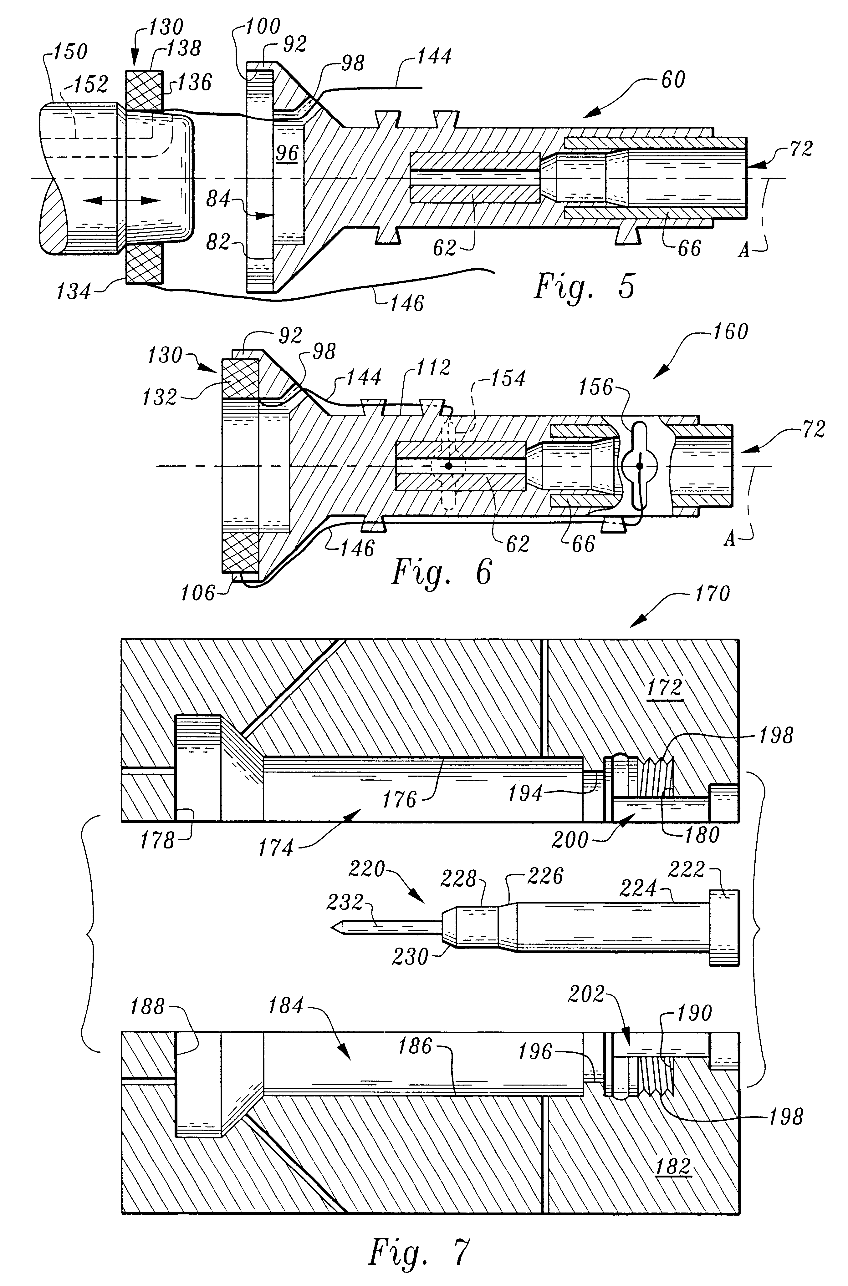
In its essence, and referring to FIG. 1, the proximity probe 10 pursuant to the present invention is comprised of an elongated encapsulated probe tip 20 having a sensing coil 130 disposed proximate a front end 22 and a cable 240 emanating from a back end 24. The elongated encapsulated probe tip 20 includes a longitudinal axis "A" and is comprised of a monolith of cured moldable material defining an encapsulation 30 ensconcing the coil 130 and a preform 60. The elongated encapsulated probe tip 20 is manufactured by first forming the preform 60. The coil 130 is then attached to the preform 60 and tuned. Once tuned, the coil 130 is permanently and electrically connected to the preform thereby completing the formation of a coil and preform assembly 160 (please see FIG. 6)...


PUM

PropertyMeasurementUnit
angleaaaaaaaaaa
electrical characteristicsaaaaaaaaaa
moldableaaaaaaaaaa

Abstract

Method of making a proximity probe including providing a preform having an interior cavity accessible by an opened rearward end; coupling a coil to the preform proximate a forward most end of the preform for defining an assembly; locating a single support pin through the rearward end such that the support pin extends within the interior cavity while having an end emanating from the rearward end; cantilevering the emanating end between an upper and a lower mold plate defining a mold cavity for supporting the assembly; injecting moldable material into the mold cavity for molding an encapsulation of material over the assembly for defining an encapsulated probe tip, allowing the encapsulated probe tip to cure; removing the encapsulated probe tip from the mold cavity; removing the support pin from the assembly, and coupling a cable to the encapsulated probe tip for forming the proximity probe.

Description

The present invention relates generally to a proximity probe and, in particular, to an encapsulated proximity probe and its manufacturing method for providing an accurate encapsulated proximity probe that is impervious to the predations of its environment and that is used to, inter alia, monitor vibration of rotating and reciprocating machinery.Proximity probe systems that analyze and monitor, for example, rotating and reciprocating machinery are known in the art. These systems typically include one or more proximity probes: noncontacting devices that measure displacement motion and position of the observed conductive target material relative to the probe. Typically, each proximity probe is located proximate a target object such as a rotating shaft of a machine or an outer race of a rolling element bearing being monitored and is connected to conditioning circuitry which in turn is coupled to analyzing apparatus for data reduction and display. By known techniques, these systems analy...

Claims


Application Information

Patent Timeline
Patent Type & Authority Patents(United States)
IPC IPC(8): G01B7/02G01B7/00
CPCG01B7/003G01B7/023Y10T29/4902Y10T29/49005Y10T29/49171Y10T29/49172Y10T29/49007Y10T29/49123Y10T29/49146Y10T29/49073
Inventor ROSE, ROBERT IVAN
Owner BENTLY NEVADA INC
Why Eureka
Try Eureka