

Wheel board vehicle
a technology of wheels and vehicles, applied in the direction of sports apparatus, bicycles, skating, etc., can solve the problems of limiting the maximum turning angle of the front yoke and the front wheel to 10.degree. or less, affecting the use of the vehicle, and causing the rider to lose balance and fall off the vehicle, etc., to achieve convenient use, increase the turning angle of the front wheel, and facilitate the rid
- Summary
- Abstract
- Description
- Claims
- Application Information
AI Technical Summary
Benefits of technology
Problems solved by technology
Method used
Image

Examples
first embodiment
A First Embodiment
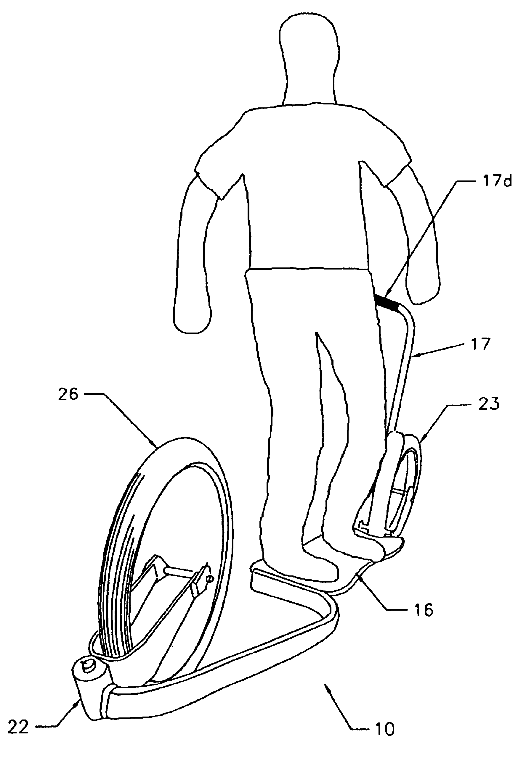
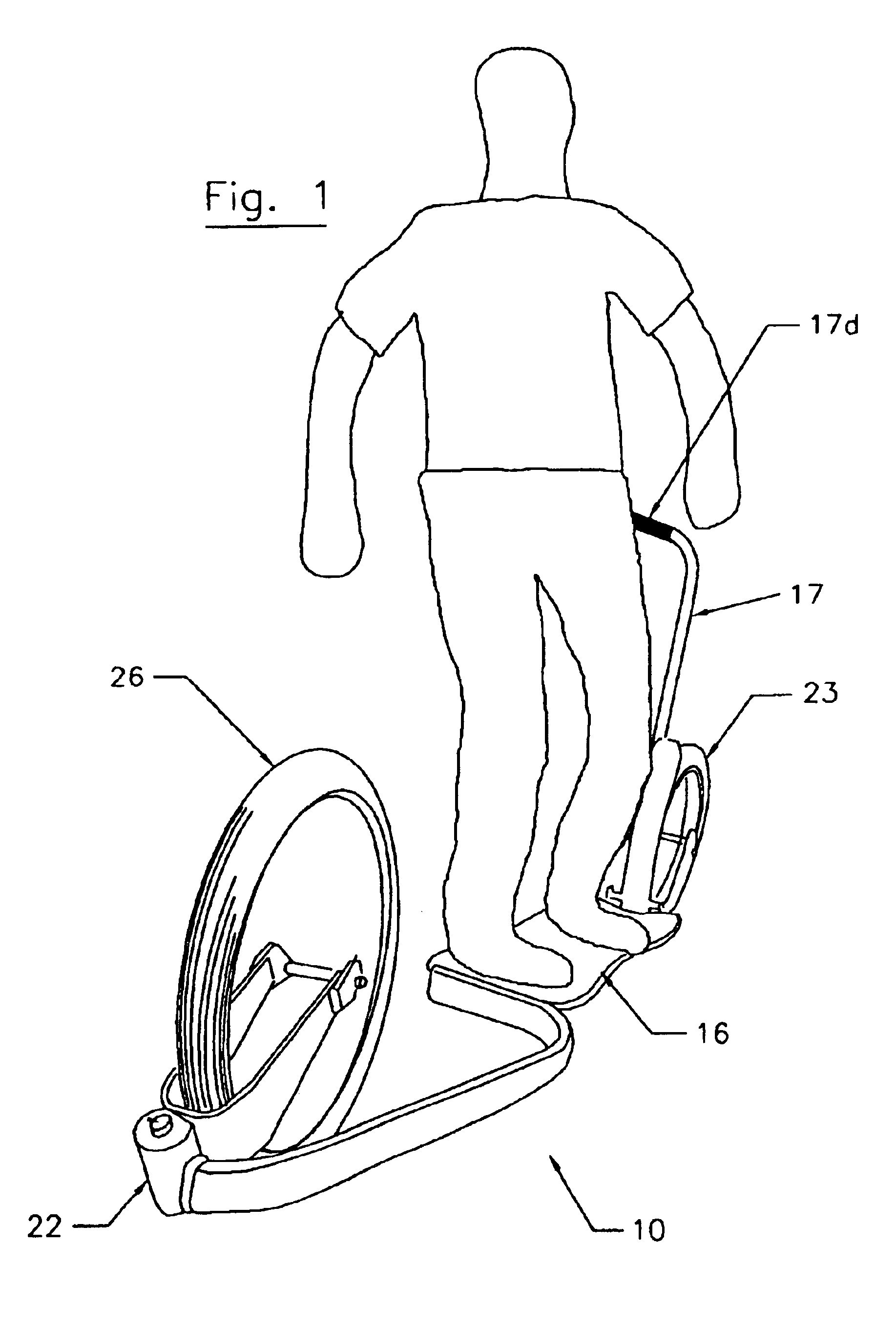
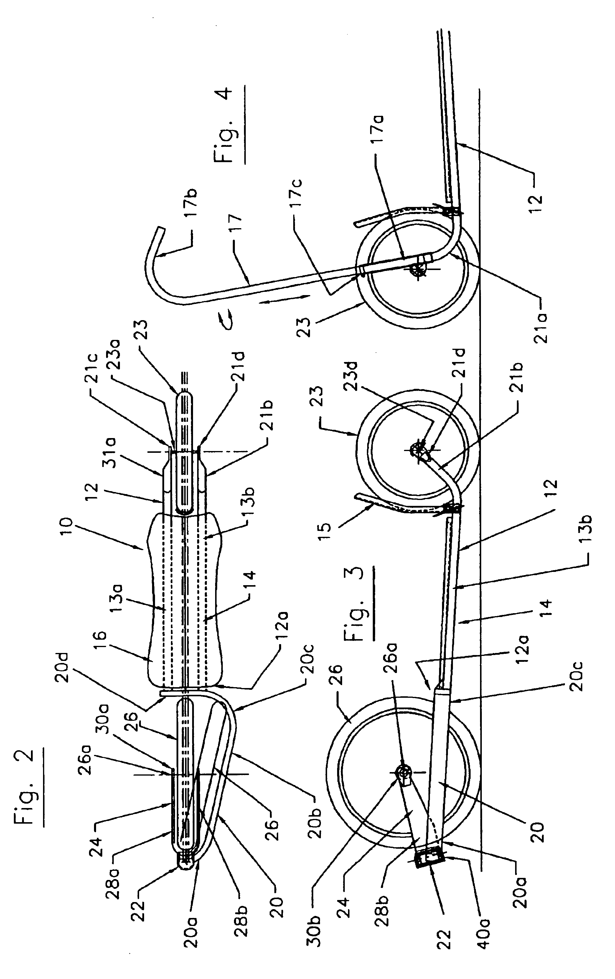
As illustrated in FIGS. 1-9, a first embodiment of this invention, the wheel board vehicle 10, includes a rigid frame 12 supporting a front spoke wheel 26, a spoke rear wheel 23, a board 16 between these wheels, and a brake 15. The width of the tires of these front and rear wheel ranges from about 1 to about 10 inches. The frame 12 comprises substantially parallel tubes 13a and 13b spaced apart from approximately 3 to 6 inches. Rearward beyond the brake 15, the tubes 13a and 13b taper inward forming a pair of substantially parallel rear support arms 21a and 21b integral with the frame 12 and spaced apart. The rear wheel 23 has its axle 23a extending between the outboard ends 21c and 21d, respectively, of the rear support arms 21a and 21b. This rear wheel 23 does not turn or pivot. It only rotates while the vehicle 10 is moving.
The frame 12 has a front end 12a from which extends a single, rigid support arm 20 having an outboard end 20a to which a pivot member 22 is ...
second embodiment
A Second Embodiment
As illustrated in FIG. 10, a second embodiment of this invention, the vehicle 60, has a single rigid support arm 62 extending from the front of the vehicle. This rigid support arm 62 is directly above and in the reference plane R, and has a substantially semi-circular configuration with an open lower side 64 through which the lower portion of the front wheel 26 projects. The pivot member 22 is attached to an outboard end 62a of this support arm 62 and is constructed substantially as discussed above to enable the yoke 24 carrying the front wheel 26 to pivot and rotate as discussed, with one major exception. Namely, the yoke 24 now has a turning angle in excess of 20 degrees equally in either a clockwise or counter-clockwise direction. The pivot shell 40 fixedly attached to the outboard end 62a has its cut-away section 40b more opened, so that the opposed sides 42a and 42b that serve as stops are more widely spaced apart than depicted in connection with the first em...
third embodiment
A Third Embodiment
As illustrated in FIG. 11, a third embodiment of this invention, the vehicle 70, is similar to the second embodiment depicted in FIG. 10 except it employs a single rigid support arm 72 positioned in the reference plane R like the arm 62 of the vehicle 60. The main difference between these vehicles 60 and 70 is that the rigid support arm 72 is made from a pair of tubes 74 and 76 that have a substantially semi-circular type construction and are parallel to each other. These parallel tubes 74 and 76 straddle the longitudinal axis X of the board 16 and are connected by cross ties 78.
PUM
 Abstract
Description
Claims
Application Information