Electronic device with force sensing key

a technology of force sensing and electronic devices, applied in the field of compact keypads, can solve the problems of user frustration, user error, and user's prone to entry errors

Active Publication Date: 2006-10-31
GOOGLE TECHNOLOGY HOLDINGS LLC
View PDF15 Cites 78 Cited by
  • Summary
  • Abstract
  • Description
  • Claims
  • Application Information

AI Technical Summary

Problems solved by technology

A user, however, is also more prone to make entry errors because the depression of the key must be precise enough to access only the desired switches and also because the tactile feedback for a multi-switch key is unfamiliar.
This user habit results in a need for changing the incorrect character entered and may eventually result in user frustration.

Method used


Image

  • Electronic device with force sensing key
  • Electronic device with force sensing key
  • Electronic device with force sensing key

Examples


first embodiment

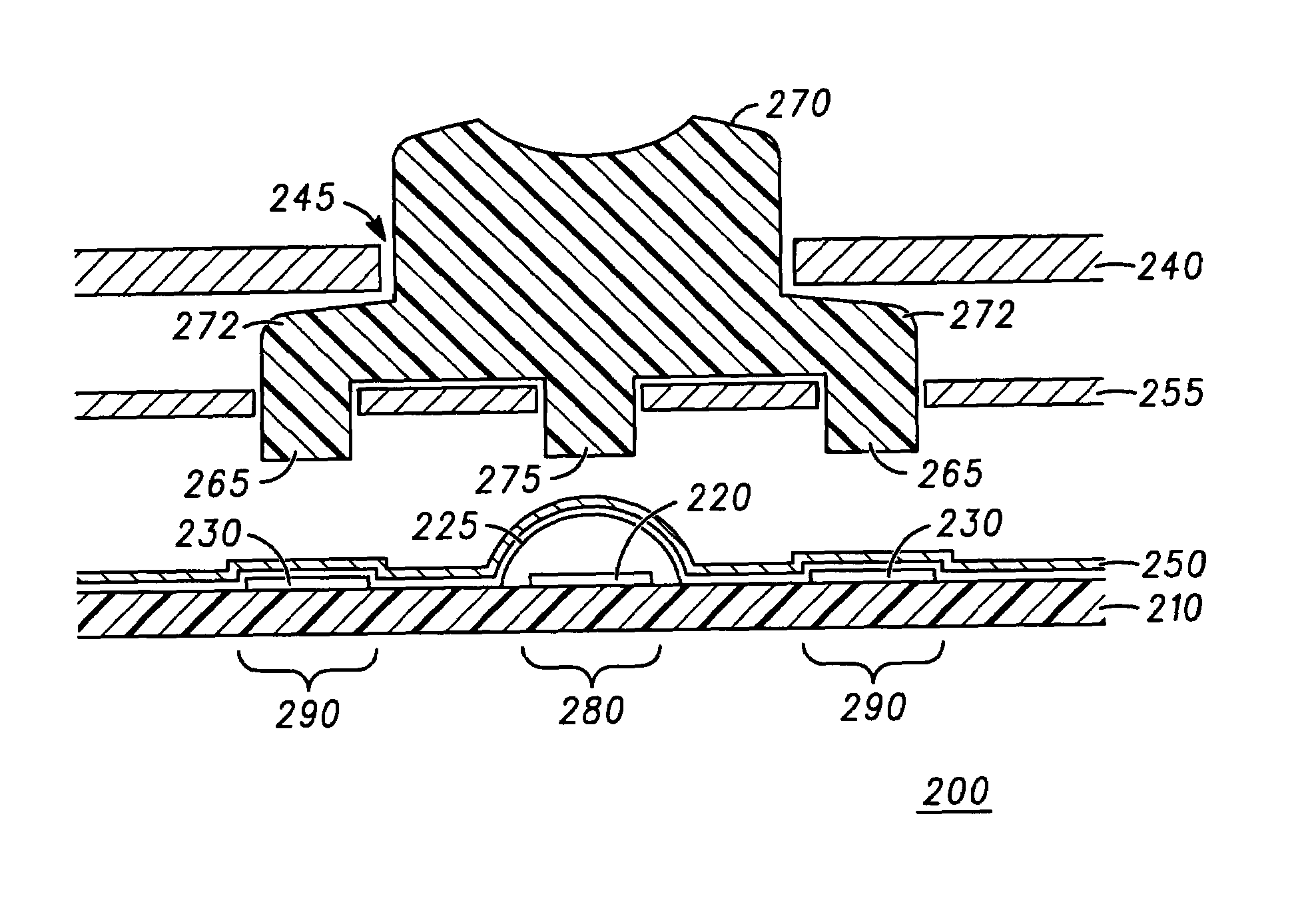
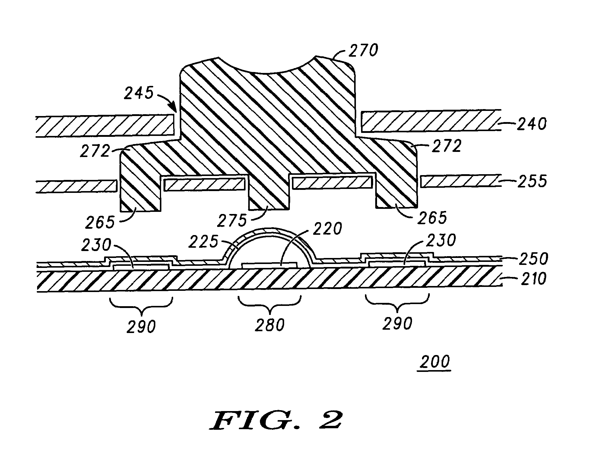
[0020]FIG. 2 shows a cross-section of a force sensing key 200 in the electronic device 100 of FIG. 1 according to a Force sensing keys, such as keys 130 in FIG. 1, use a force sensing material to gauge how much pressure is being applied to multiple force sensing pads 290 of the key 200. The force measurement is evaluated when a central switch 280 closes due to external pressure on an actuator 270.

[0021]The various components of the force sensing key 200 are supported on a common substrate 210, such as printed circuit board material. Alternate constructions include printed circuitry on a flexible substrate supported by metal, plastic, or other rigid base. In at least one embodiment, the common substrate 210 is generally planar.

[0022]A central switch 280 is formed using a switch contact 220 on a surface of the common substrate 210. Interleaving conductive traces usually form central switch contact 220 topographies, so that a conductive popple dome 225 pressed against the conductive t...

second embodiment

[0032]FIG. 4 shows a cross-section of a force sensing key 400 in the electronic device 100 of FIG. 1 according to a A force sensing key, such as keys 130 in FIG. 1, uses a force sensing material to gauge how much pressure is being applied to multiple force sensing pads 490 of the key 400. The force measurement is evaluated when a central switch 480 closes due to external pressure on an actuator 470.

[0033]The actuator 470 has a key cap 471 formed from a hard plastic material and includes a flange 472 and a central plunger 475. A hard plastic key cap 471 has a top contact surface that provides a solid feel to a user, and the hard plastic helps distribute the force of a keypress to the central switch 480 and the satellite force sensing pads 490. The key cap 471 is attached to a pad 455 which forms the underside of the composite actuator 470. The pad 455 is formed from a soft material such as silicon. The pad 455 aligns and supports the key cap 471 and also provides a bottom contact su...


PUM

PropertyMeasurementUnit
forceaaaaaaaaaa
thresholdaaaaaaaaaa
pressureaaaaaaaaaa

Abstract

An electronic device with a force sensing key (200) has a switch (280), a first force sensing region (290) for acquiring a first force value, a second force sensing region (290) for acquiring a second force value, and a processor for determining a selected function for the key (200) based upon the first force value and the second force value when the switch (280) is activated. The first force sensing pad (290) and the second force sensing pad (290) use a partially resistive material (250) that exhibits a force-to-voltage response value. By forming the switch (280) as a dome (225) switch, the force sensing key (200) provides crisp tactile feedback to a user. The force sensing key (200) can be configured for a variety of applications and user preferences by varying the architecture of the actuator (270).

Description

FIELD OF THE DISCLOSURE[0001]This disclosure relates generally to compact keypads for devices such as fixed telephones, mobile telephones, personal digital assistants (PDAs), and remote controllers.BACKGROUND OF THE DISCLOSURE[0002]A compact keypad for a telephone, PDA, remote controller, or similar device typically has between twelve and twenty keys for controlling the operation of the device. The keys generally include: number keys “0”–“9”; telephony keys “*” and “#”; and keys for additional functions such as “menu”, “cancel”, “cursor up”, “cursor down,”“cursor right,”“cursor left,” and “select”. In at least some instances, the device's size impacts the number of keys that can be conveniently accessed.[0003]In order to increase the number of functions available through a device (or maintain a constant number of functions in light of decreasing device size), often several keys in the compact keypad are associated with multiple functions and / or meanings in order to enable the increa...

Claims


Application Information

Patent Timeline
Patent Type & Authority Patents(United States)
IPC IPC(8): H04B1/10H04B7/00H04M1/66G06F3/023H01H13/70H01H13/785H03K17/94H03M11/00H04N5/44
CPCG06F3/0234H01H13/7006H01H13/785H04N21/42212H01H2217/036H01H2221/012H04N2005/4416H01H2201/036H03K17/94
Inventor ARNESON, THEODORE R.CHARLIER, MICHAEL L.
Owner GOOGLE TECHNOLOGY HOLDINGS LLC
Why Eureka
Try Eureka