Impedance source power converter

a power converter and source technology, applied in the direction of dc-ac conversion without reversal, process and machine control, instruments, etc., can solve the problems of increasing system cost, reducing system efficiency, and v-converter having a number of conceptual and theoretical limitations

Active Publication Date: 2006-10-31
MICHIGAN STATE UNIV
View PDF11 Cites 70 Cited by
  • Summary
  • Abstract
  • Description
  • Claims
  • Application Information

AI Technical Summary

Problems solved by technology

The V-converter has a number of conceptual and theoretical limitations.
However, such a DC-DC boost converter stage increases system cost and lowers system efficiency.
With reference to FIG. 1, the upper and lower devices (i.e., the switch pairs S1/S2, S3/S4 and S5/S6) of each phase leg cannot be gated on simultaneously or a shoot-through occurs, which may cause the upper and lower devices to be destroyed.
Further, an output LC filter, which also causes additional power loss and increases control complexity, is required to provide a sinusoidal voltage at the output of the V-converter 100.
Unfortunately, an

Method used


Image

  • Impedance source power converter
  • Impedance source power converter
  • Impedance source power converter

Examples


Embodiment Construction

)

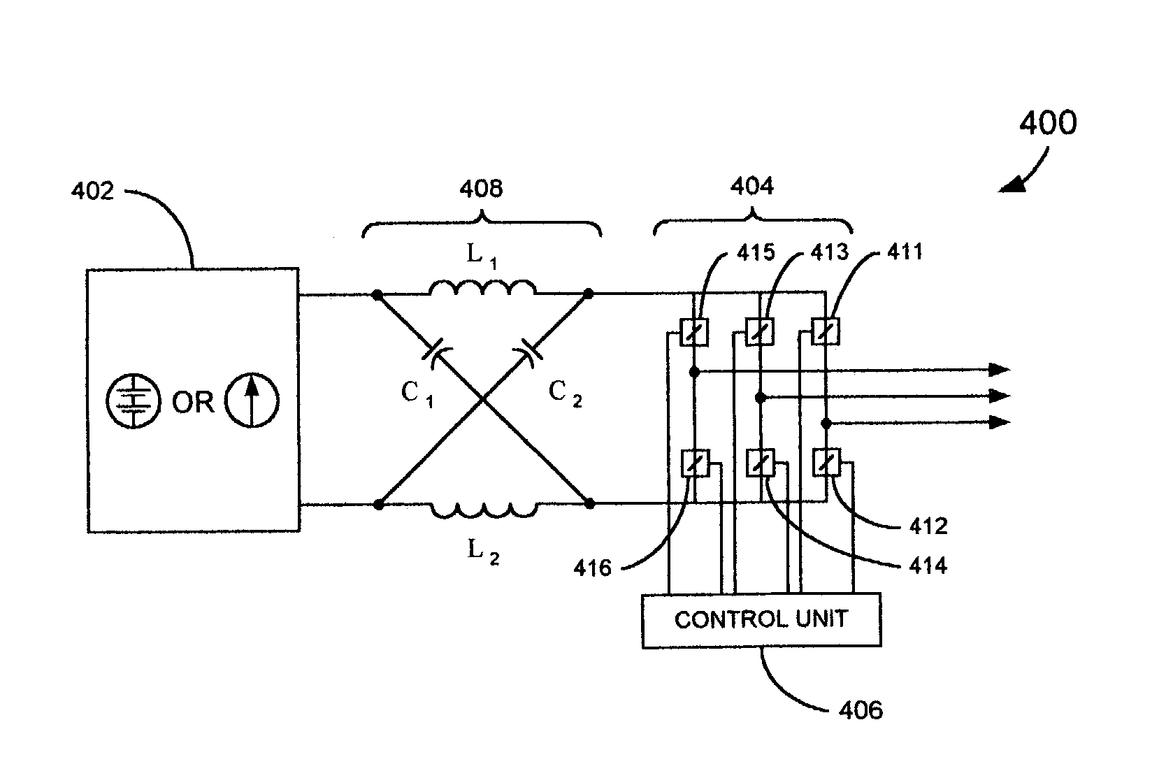
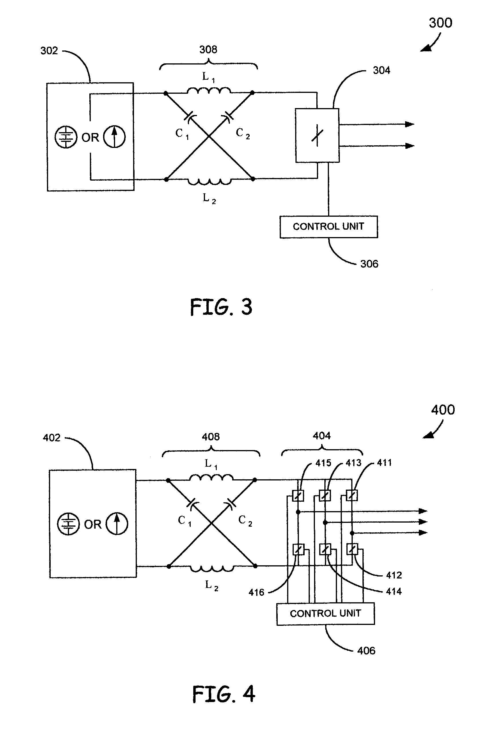
[0028]According to the present invention, an impedance source power converter (Z-converter) utilizes an impedance network to couple a main converter circuit to a power source or load. Implementation of the impedance network, within the power converter, reduces or eliminates many of the negative attributes of V-converters and / or I-converters. As used herein, the term “converter” broadly includes DC-DC converters, AC-AC converters, converters performing AC-DC conversion and inverters performing DC-AC conversion.

[0029]FIG. 3 shows one embodiment of the present invention, which includes a two port network 308 that includes inductors L1 and L2 and capacitors C1 and C2 connected in an ‘X’ configuration. The ‘X’ configuration is employed to provide an impedance source to couple the converter (or inverter) to a DC source 302. The DC source 302 can be either a voltage source or a current source. As such, the DC source 302 can be a battery, a diode rectifier, a thyristor converter, a fuel ce...


PUM


Abstract

An impedance source power converter includes a power source, a main converter circuit and an impedance network. The main converter circuit is coupled to a load and the impedance network couples the power source to the main converter circuit. The impedance network is configured such that the main converter circuit is adapted to perform both buck conversion and boost conversion.

Description

[0001]This application claims the benefit of U.S. Provisional Patent Application Ser. No. 60 / 388,206, entitled “IMPEDANCE SOURCE POWER CONVERTER,” which was filed Jun. 12, 2002, and which is hereby incorporated herein by reference in its entirety.BACKGROUND OF THE INVENTION[0002]The present invention is directed to a power converter and, more specifically, an impedance source power converter.[0003]Power converters are utilized in various applications and have traditionally been constructed as either voltage source converters (V-converters) or current source converters (I-converters). In a typical V-converter, a DC voltage source feeds a main converter circuit, for example, a three-phase bridge. The DC voltage source may take various forms, such as a battery, a fuel cell stack, a diode rectifier and / or a capacitor. In a typical three-phase bridge, six switches are utilized to implement the main converter circuit. FIG. 1 depicts a traditional three-phase V-converter 100, which include...

Claims


Application Information

Patent Timeline
IPC IPC(8): H02M7/537H02M7/48
CPCH02M7/48H02M7/4826
Inventor PENG, FANG Z.
Owner MICHIGAN STATE UNIV
Why Eureka
Try Eureka